ST203C686MAJ03 AVX Corporation, ST203C686MAJ03 Datasheet - Page 80
ST203C686MAJ03
Manufacturer Part Number
ST203C686MAJ03
Description
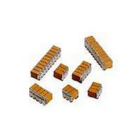
CAP CER 68UF 25V STACKED SMD
Manufacturer
AVX Corporation
Series
TurboCap™r
Specifications of ST203C686MAJ03
Capacitance
68µF
Tolerance
±20%
Temperature Coefficient
X7R
Voltage - Rated
25V
Mounting Type
Surface Mount, MLCC
Operating Temperature
-55°C ~ 125°C
Features
Stacked
Applications
Filtering Switch Mode Power Supplies
Package / Case
6-Stacked SMD, J-Lead
Size / Dimension
0.325" L x 0.300" W (8.26mm x 7.62mm)
Thickness
5.59mm Max
Lead Style
J-Lead
Voltage Rating
25 Volts
Operating Temperature Range
- 55 C to + 125 C
Product
General Type MLCCs
Dielectric Characteristic
X7R
Capacitance Tolerance
± 20%
Capacitor Case Style
DIP
No. Of Pins
6
Capacitor Mounting
SMD
Rohs Compliant
No
Termination Style
Radial
Lead Spacing
6.35 mm
Dimensions
7.62 mm W x 8.26 mm L x 5.59 mm H
Dissipation Factor Df
2.5
Lead Free Status / RoHS Status
Contains lead / RoHS non-compliant
Ratings
-
Lead Spacing
-
Lead Free Status / RoHS Status
Contains lead / RoHS non-compliant
Other names
478-6117


General Description
Effects of Time – Class 2 ceramic capacitors change
capacitance and dissipation factor with time as well as
temperature, voltage and frequency. This change with time is
known as aging. Aging is caused by a gradual re-alignment
of the crystalline structure of the ceramic and produces an
exponential loss in capacitance and decrease in dissipation
factor versus time. A typical curve of aging rate for semi-
stable ceramics is shown in Figure 4.
If a Class 2 ceramic capacitor that has been sitting on the
shelf for a period of time, is heated above its curie point,
(125°C for 4 hours or 150°C for
will de-age and return to its initial capacitance and dissi-
pation factor readings. Because the capacitance changes
rapidly, immediately after de-aging, the basic capacitance
measurements are normally referred to a time period some-
time after the de-aging process. Various manufacturers use
different time bases but the most popular one is one day
or twenty-four hours after “last heat.” Change in the aging
curve can be caused by the application of voltage and
other stresses. The possible changes in capacitance due to
de-aging by heating the unit explain why capacitance changes
are allowed after test, such as temperature cycling, moisture
resistance, etc., in MIL specs. The application of high voltages
such as dielectric withstanding voltages also tends to de-age
capacitors and is why re-reading of capacitance after 12 or 24
hours is allowed in military specifications after dielectric
strength tests have been performed.
+1.5
-3.0
-4.5
-1.5
-6.0
-7.5
0
1
Characteristic
C0G (NP0)
X7R, X5R
Typical Curve of Aging Rate
10
100
Figure 4
Max. Aging Rate %/Decade
X7R
Hours
1000 10,000 100,000
1
⁄
2
hour will suffice) the part
None
2
Effects of Frequency – Frequency affects capacitance
and impedance characteristics of capacitors. This effect is
much more pronounced in high dielectric constant ceramic
formulation than in low K formulations. AVX’s SpiCalci
software generates impedance, ESR, series inductance,
series resonant frequency and capacitance all as functions
of frequency, temperature and DC bias for standard chip
sizes and styles. It is available free from AVX and can be
downloaded for free from AVX website: www.avx.com.
Effects of Mechanical Stress – High “K” dielectric ceramic
capacitors exhibit some low level piezoelectric reactions
under mechanical stress. As a general statement, the piezo-
electric output is higher, the higher the dielectric constant of
the ceramic. It is desirable to investigate this effect before
using high “K” dielectrics as coupling capacitors in extreme-
ly low level applications.
Reliability – Historically ceramic capacitors have been one
of the most reliable types of capacitors in use today.
The approximate formula for the reliability of a ceramic
capacitor is:
where
Historically for ceramic capacitors exponent X has been
considered as 3. The exponent Y for temperature effects
typically tends to run about 8.
L
V
L
V
o
o
t
t
= operating life
= test life
= test voltage
= operating voltage
L
L
o
t
=
V
V
o
t
X
X,Y = see text
T
T
T
T
o
o
t
t
= test temperature and
= operating temperature
Y
in °C
79
Related parts for ST203C686MAJ03
Image
Part Number
Description
Manufacturer
Datasheet
Request
R

Part Number:
Description:
Inverter Grade Thyristors
Manufacturer:
International Rectifier Corp.
Datasheet:

Part Number:
Description:
Manufacturer:
AVX Corporation
Datasheet:
Part Number:
Description:
Manufacturer:
AVX Corporation
Datasheet:
Part Number:
Description:
Manufacturer:
AVX Corporation
Datasheet:
Part Number:
Description:
Manufacturer:
AVX Corporation
Datasheet: