C1210Y103K2RACTU Kemet, C1210Y103K2RACTU Datasheet
C1210Y103K2RACTU
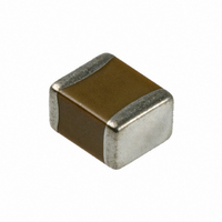
Specifications of C1210Y103K2RACTU
C1210Y103K2RAC7800


Related parts for C1210Y103K2RACTU

C1210Y103K2RACTU Summary of contents
Page 1
... Additional reeling or packaging options may be available. Contact KEMET for details. 2 One WORLD © KEMET Electronics Corporation • P.O. Box 5928 • Greenville, SC 29606 (864) 963-6300 • www.kemet.com environmental and/or handling conditions, the combination of these two technologies provide the ultimate level of protection against a low IR or short circuit condition ...
Page 2
... AEC-Q200, Stress Test Qualification for Passive Components. For additional information regarding the Automotive Electronics Council and AEC-Q200, please visit their website @www.aecouncil.com. Environmental Compliance RoHS PRC ( Peoples Republic of China) compliant © KEMET Electronics Corporation • P.O. Box 5928 • Greenville, SC 29606 (864) 963-6300 • www.kemet.com ...
Page 3
... KEMET Electronics Corporation • P.O. Box 5928 • Greenville, SC 29606 (864) 963-6300 • www.kemet.com Operating Temperature Range: -55°C to +125°C ±15% 3.5% 250% of rated voltage (5 ± 1 seconds and charge/discharge not exceeding Dielectric Withstanding Voltage: 50mA) 5%(10V), 3.5%(16V & ...
Page 4
... Y = Floating 2 Sig. Digits + 0805 Electrode Number of Zeros 1206 w/ Flexible 1210 Termination 1812 © KEMET Electronics Corporation • P.O. Box 5928 • Greenville, SC 29606 (864) 963-6300 • www.kemet.com C0603Y Product Availability and Chip Thickness Codes - See Table 2 for Chip Thickness Dimensions CB CB ...
Page 5
... Code Series C 0805 Y Case Size Specifi cation/ Ceramic (L" x W") Series 0603 Y = Floating 2 Sig. Digits + 0805 Electrode Number of Zeros 1206 w/ Flexible 1210 Termination 1812 © KEMET Electronics Corporation • P.O. Box 5928 • Greenville, SC 29606 (864) 963-6300 • www.kemet.com C1206Y ...
Page 6
... KC 2225 KD 2225 KE 2225 KF 2225 © KEMET Electronics Corporation • P.O. Box 5928 • Greenville, SC 29606 (864) 963-6300 • www.kemet.com Qty per Reel Qty per Reel 7" Plastic 13" Plastic 0.20 ± 0.02 0.30 ± 0.03 0.50 ± 0.05 0.80 ± 0.07 0.80 ± ...
Page 7
... Density Level C: For high component density product applications. Before adapting the minimum land pattern variations the user should perform qualification testing based on the conditions outlined in IPC standard 7351 (IPC-7351). © KEMET Electronics Corporation • P.O. Box 5928 • Greenville, SC 29606 (864) 963-6300 • www.kemet.com Density Level B: ...
Page 8
... MIL-STD-202 Method 213 Resistance to Solvents MIL-STD-202 Method 215 © KEMET Electronics Corporation • P.O. Box 5928 • Greenville, SC 29606 (864) 963-6300 • www.kemet.com Test or Inspection Method Reflow solder the capacitor onto a PC board and apply voltage with 10kHz~1Mhz sine curve. (Ripple voltage must be < rated voltage) Appendix 1, Note: Force of 1 ...
Page 9
... Array 0508 & 0612 8 *Refer to Figure 1 for W and P carrier tape reference locations. 1 *Refer to Table 6 for tolerance specifications. © KEMET Electronics Corporation • P.O. Box 5928 • Greenville, SC 29606 (864) 963-6300 • www.kemet.com Bar Code Label Anti-Static Reel Embossed Plastic* or Punched Paper Carrier. Sprocket Holes ...
Page 10
... B are measured on a plane 0.3mm above the bottom of the pocket (f) see Addendum in EIA Document 481 for standards relating to more precise taping requirements. © KEMET Electronics Corporation • P.O. Box 5928 • Greenville, SC 29606 (864) 963-6300 • www.kemet.com P 2 [10 pitches cumulative Po tolerance on tape ± ...
Page 11
... Figure 4). e) see Addendum in EIA Document 481 for standards relating to more precise taping requirements. 2. The tape with or without components shall pass around R without damage (see Figure 5). © KEMET Electronics Corporation • P.O. Box 5928 • Greenville, SC 29606 (864) 963-6300 • www.kemet.com P 2 ...
Page 12
... Tape 0.5 mm maximum 0.5 mm maximum Figure 5 – Bending Radius Embossed Punched Carrier Carrier Bending R R Radius © KEMET Electronics Corporation • P.O. Box 5928 • Greenville, SC 29606 (864) 963-6300 • www.kemet.com Peel Strength Maximum Component Rotation Maximum ° ° s Rotation ( ) ...
Page 13
... Tape Size N Min 8mm 12mm (1.969) 16mm © KEMET Electronics Corporation • P.O. Box 5928 • Greenville, SC 29606 (864) 963-6300 • www.kemet.com Access Hole at Slot Location (Ø min.) C (Arbor hole diameter) If present, tape slot in core for tape start: 2 ...
Page 14
... Figure 8 – Maximum Camber Elongated sprocket holes (32 mm & wider tapes maximum, either direction Straight Edge 250 mm © KEMET Electronics Corporation • P.O. Box 5928 • Greenville, SC 29606 (864) 963-6300 • www.kemet.com Carrier Tape Round Sprocket Holes START 100 mm Min. Leader ...
Page 15
... Table 10 – Capacitor Marking Laser marking is available as an extra-cost option for most KEMET ceramic chips. Such marking is two sided, and includes identify KEMET, followed by two characters (per EIA-198) to identify the capacitance value. Note that marking is not available for any Y5V chip. ln addition, the 0603 marking option is limited to the K only. (Marking Optional – ...
Page 16
... Although all product-related warnings, cautions and notes must be observed, the customer should not assume that all safety measures are indicated or that other measures may not be required. © KEMET Electronics Corporation • P.O. Box 5928 • Greenville, SC 29606 (864) 963-6300 • www.kemet.com Tools http://capacitoredge ...
Page 17
... Fax: 44-1279-465237 Note: KEMET reserves the right to modify minor details of internal and external construction at any time in the interest of product improvement. KEMET does not assume any responsibility for infringement that might result from the use of KEMET Capacitors in potential circuit designs. KEMET is a registered trademark of KEMET Electronics Corporation. © ...