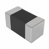
C0603T470J5GCLTU Kemet, C0603T470J5GCLTU Datasheet - Page 3

C0603T470J5GCLTU
Manufacturer Part Number
C0603T470J5GCLTU
Description
CAP CER 47PF 50V C0G 0603
Manufacturer
Kemet
Specifications of C0603T470J5GCLTU
Capacitance
47pF
Voltage - Rated
50V
Tolerance
±5%
Temperature Coefficient
C0G, NP0
Mounting Type
Surface Mount, MLCC
Operating Temperature
-55°C ~ 125°C
Applications
General Purpose
Ratings
COTS
Package / Case
0603 (1608 Metric)
Size / Dimension
0.063" L x 0.031" W (1.60mm x 0.80mm)
Thickness
0.80mm
Lead Free Status / RoHS Status
Contains lead / RoHS non-compliant
Features
-
Lead Spacing
-
Other names
C0603T470J5GCL
C0603T470J5GCL7867
C0603T470J5GCL7867
© KEMET Electronics Corporation • P.O. Box 5928 • Greenville, SC 29606 • (864) 963-6300 • www.kemet.com
These chips are supplied unmarked. If required, they can be laser-marked as an extra cost option. Details on the
marking format are included in KEMET Surface Mount Catalog F3102.
The 0402 size is suitable for solder reflow only. The 0603, 0805 and 1206 sizes are suitable for either reflow or
wave soldering. Sizes 1210 and larger should be limited to reflow soldering only.
EIA Case Sizes
Capacitance Range
Test Parameters
Operating Temperature Range -55°C to +125°C, with no bias capacitance shift limited to ±15% over that range
Capacitance Tolerances
Aging Rate
Voltage Rating
25°C IR @ Rated Voltage
Dielectric Strength (DWV)
Chip Size
0402
0603
0805
1206
1210
1812
1825
2220
2225
T - Total Length S - Separation
2.14
2.78
3.30
4.50
4.50
5.90
5.90
7.00
7.00
Recommended Solder Pad Dimensions
mm
General Performance Characteristics & Electrical Parameters
0.084
0.109
0.130
0.177
0.177
0.232
0.232
0.275
0.275
in.
0402, 0603, 0805, 1206, 1210, 1812, 1825, 2220, 2225
0.5pF – 22.0μF
Capacitance and Dissipation Factor measured at: C0G – 1kHz and 1 Vrms if capacitance
1000pF and 1MHz and 1 Vrms if capacitance ≤1000pF. X7R – 1kHz and 1 Vrms if capaci-
tance ≤10μF and 120Hz and 0.5 Vrms if capacitance >10μF.
B = ±.10pF; C = ± 0.25pF; D = ±0.5pF; F = ±1%; G = ±2%; J = ±5%, K = ±10%, M = ±20%
C0G – 0% maximum; X7R –2.0% maximum % capacitance loss/decade hour
6.3; 10; 16; 25; 50; 100; 200 Volts
1000MΩ−μF or 100GΩ, whichever is less
2.5 times rated DC voltage
0.28
0.68
0.70
1.50
1.50
2.30
2.30
3.30
3.30
mm
0.027
0.028
0.059
0.059
0.091
0.091
0.011
0.13
0.13
in.
Soldering Process
W - Pad Width L - Pad Length
0.74
1.08
1.60
2.00
2.90
3.70
6.90
5.50
6.80
mm
Marking
0.029
0.043
0.063
0.079
0.146
0.272
0.216
0.268
0.114
in.
0.93
1.05
1.30
1.50
1.50
1.80
1.80
1.85
1.85
mm
0.037
0.041
0.051
0.059
0.059
0.071
0.071
0.073
0.073
in.


