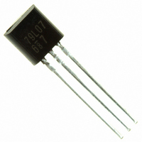
AN79L07 Panasonic - SSG, AN79L07 Datasheet

AN79L07
Specifications of AN79L07
Available stocks
Related parts for AN79L07
AN79L07 Summary of contents
Page 1
... DATA SHEET Part No. Package Code No. Publication date: January 2008 AN79L07 SSIP003-P-0000S (Exclusive use for AN79Lxx) SFF00114AEB 1 ...
Page 2
... AN79L07 Overview ……………………………………………………………………………………………………………. 3 Features … ...
Page 3
... Stabilized fixed output voltage is obtained from unstable DC input voltage without using any external components. 12 types of output voltage are available; –4 V, –5 V, –6 V, –7 V, –8 V, –9 V, –10 V, –12 V, –15 V, –18 V, –20 V and –24 V. They can be used widely in power circuits with current capacity 100 mA. The AN79L07 is the –7 V output voltage type in these series. Features No external components Output voltage: – ...
Page 4
... AN79L07 Block Diagram Starter When a wiring from a smoothing circuit to a three-pin regulator is long likely to oscillate at IN output. A capacitor of 0.1 μF to 0.47 μF should be connected near an input pin. : Deadly needed to prevent from oscillation (0.33 μF to 1.0 μ recommended to use a capacitor C OUT of a small internal impedance (ex. tantalum capacitor) when using it under a low temperature. ...
Page 5
... AN79L07 Application Circuit Example Adjustable output regulator – μ OUT Note) −V varies due to sample to sample variation of I OUT Never fail to adjust individually with R Input 2 1 Common I Bias ⎛ ⎝ R ⎜ ⎜ OUT ⎝ ⎛ SFF00114AEB Output –V OUT OUT μF ...
Page 6
... AN79L07 Pin Descriptions Pin No. Pin name Type 1 Output Output 2 Common GND 3 Input Input Regulated power output Ground Input supplies power to the internal circuitry SFF00114AEB Description 6 ...
Page 7
... AN79L07 Absolute Maximum Ratings A Parameter No. 1 Input voltage 2 Supply current 3 Power dissipation 4 Operating ambient temperature 5 Storage temperature Note) *1: The values under the condition not exceeding the above absolute maximum ratings and the power dissipation. *2: Since current limiting circuit is built in, current value never exceeds the limit. ...
Page 8
... AN79L07 Electrical Characteristics = 25°C±2°C, V Note) Unless otherwise specified Parameter No. 1 Output voltage 2 Line regulation 3 Load regulation 4 Bias current 5 Bias current fluctuation to input 6 Bias current fluctuation to load 7 Ripple rejection ratio Note) *1: The specified condition T = 25°C means that the test should be carried out within so short a test time (within 10ms) that the characteristic j value drift due to the chip junction temperature rise can be ignored ...
Page 9
... AN79L07 Electrical Characteristics (Reference values for design) Note) Unless otherwise specified 25°C±2° The characteristics listed below are reference values for design of the IC and are not guaranteed by inspection problem does occur related to these characteristics, Matsushita will respond in good faith to user concerns. ...
Page 10
... AN79L07 Technical Data P — T diagram D a SFF00114AEB 10 ...
Page 11
... AN79L07 Package Dimensions (Unit: mm) SSIP003-P-0000S (Exclusive use for AN79Lxx) SFF00114AEB 11 ...
Page 12
... AN79L07 Usage Notes 1. Short-circuit between the input pin and the GND pin If the input pin is short-circuitted to GND pin or is cut off when a large capacitance capacitor has been connected to the IC's load, a voltage of a capacitor connected to an output pin is applied between input/output of the IC and this likely results in damage of the IC ...
Page 13
Request for your special attention and precautions in using the technical information and (1) If any of the products or technical information described in this book exported or provided to non-residents, the laws and regulations of the ...


