UMK107C5105KA-T Taiyo Yuden, UMK107C5105KA-T Datasheet - Page 14
UMK107C5105KA-T
Manufacturer Part Number
UMK107C5105KA-T
Description
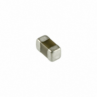
CAP CER 1.0UF 50V X5S 0603
Manufacturer
Taiyo Yuden
Series
UMKr
Datasheet
1.UMK107C5105KA-T.pdf
(19 pages)
Specifications of UMK107C5105KA-T
Capacitance
1.0µF
Voltage - Rated
50V
Tolerance
±10%
Temperature Coefficient
X5S
Mounting Type
Surface Mount, MLCC
Operating Temperature
-55°C ~ 85°C
Applications
General Purpose
Package / Case
0603 (1608 Metric)
Size / Dimension
0.063" L x 0.031" W (1.60mm x 0.80mm)
Thickness
0.80mm
Lead Free Status / RoHS Status
Lead free / RoHS Compliant
Features
-
Ratings
-
Lead Spacing
-
Other names
587-1257-2
CE UMK107 C105KA-T
UMK107C105KA-T
CE UMK107 C105KA-T
UMK107C105KA-T


Precautions on the use of Multilayer Ceramic Capacitors
1.Circuit Design
2.PCB Design
PRECAUTIONS
Stages
Verification of operating environment, electrical rating and per-
formance
1. A malfunction in medical equipment, spacecraft, nuclear re-
Operating Voltage (Verification of Rated voltage)
1. The operating voltage for capacitors must always be lower
2. Even if the applied voltage is lower than the rated value, the
Pattern configurations
(Design of Land-patterns)
1. When capacitors are mounted on a PCB, the amount of sol-
actors, etc. may cause serious harm to human life or have
severe social ramifications. As such, any capacitors to be
used in such equipment may require higher safety and/or reli-
ability considerations and should be clearly differentiated from
components used in general purpose applications.
than their rated values.
If an AC voltage is loaded on a DC voltage, the sum of the two
peak voltages should be lower than the rated value of the ca-
pacitor chosen. For a circuit where both an AC and a pulse
voltage may be present, the sum of their peak voltages should
also be lower than the capacitor's rated voltage.
reliability of capacitors might be reduced if either a high fre-
quency AC voltage or a pulse voltage having rapid rise time is
present in the circuit.
der used (size of fillet) can directly affect capacitor performance.
Therefore, the following items must be carefully considered in
the design of solder land patterns:
(1) The amount of solder applied can affect the ability of chips
(2) When more than one part is jointly soldered onto the same
to withstand mechanical stresses which may lead to break-
ing or cracking. Therefore, when designing land-patterns
it is necessary to consider the appropriate size and con-
figuration of the solder pads which in turn determines the
amount of solder necessary to form the fillets.
land or pad, the pad must be designed so that each
component's soldering point is separated by solder-re-
sist.
Precautions
Size
1.The following diagrams and tables show some examples of recommended patterns to
Recommended land dimensions for wave-soldering (unit: mm)
Recommended land dimensions for reflow-soldering (unit: mm)
Excess solder can affect the ability of chips to withstand mechanical stresses. Therefore,
please take proper precautions when designing land-patterns.
Size
prevent excessive solder amourts.flarger fillets which extend above the component end
terminationsg
Examples of improper pattern designs are also shown.
Type
Type
Type
(1) Recommended land dimensions for a typical chip capacitor land patterns for PCBs
Type
A
B
C
A
B
C
a
b
d
a
b
d
c
c
W
W
W
L
L
L
W
L
0.20V0.30 0.45V0.55 0.6V0.8 0.8V1.2 1.8V2.5 1.8V2.5 2.5V3.5
0.20V0.30 0.40V0.50 0.6V0.8 0.8V1.2 1.0V1.5 1.0V1.5 1.5V1.8
0.25V0.40 0.45V0.55 0.6V0.8 0.9V1.6 1.2V2.0 1.8V3.2 2.3V3.5
316(4 circuits)
212(2 circuits)
0.8V1.0
0.5V0.8
0.6V0.8
063
0.6
0.3
107
1.6
0.8
0.7V0.9
0.4V0.5
0.5V0.6
0.5V0.6
0.5V0.6
1.25
2.0
1.0
3.2
1.6
0.8
1
105
1.0
0.5
1.0V1.4
0.8V1.5
0.9V1.2
51.25
212
2.0
212(4 circuits)
110(2 circuits)
Technical considerations
107
1.6
0.8
0.35V0.45
0.55V0.65
1.8V2.5
0.8V1.7
1.2V1.6
0.5V0.6
0.5V0.6
0.2V0.3
0.3V0.4
316
1.25
1.37
0.64
3.2
1.6
1.0
2.0
0.5
51.25
212
2.0
1.8V2.5
0.8V1.7
1.8V2.5
325
3.2
2.5
316
3.2
1.6
325
3.2
2.5
432
4.5
3.2
1/6
87
4
Related parts for UMK107C5105KA-T
Image
Part Number
Description
Manufacturer
Datasheet
Request
R

Part Number:
Description:
Manufacturer:
Taiyo Yuden
Datasheet: