TV04A640JB-G Comchip Technology, TV04A640JB-G Datasheet - Page 28
TV04A640JB-G
Manufacturer Part Number
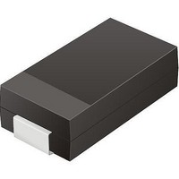
TV04A640JB-G
Description
TVS 400W 64V BIDIRECT SMA
Manufacturer
Comchip Technology
Specifications of TV04A640JB-G
Voltage - Reverse Standoff (typ)
64V
Voltage - Breakdown
71.1V
Power (watts)
400W
Polarization
Bidirectional
Mounting Type
Surface Mount
Package / Case
DO-214AC, SMA
Channels
1 Channel
Clamping Voltage
103 V
Operating Voltage
3.5 V
Breakdown Voltage
71.1 V
Peak Surge Current
40 A
Peak Pulse Power Dissipation
400 W
Lead Free Status / RoHS Status
Lead free / RoHS Compliant


28
11.7.2
11.7.3
Parallel Mode
Status Register Bit Descriptions
PO[7-0]
When the device is in Parallel Mode, the maximum SCK clock frequency is 10 MHz. The device requires a
single clock cycle instead of eight clock cycles to access the next data byte. The method of memory content
output will be the same compared to outside of Parallel Mode. The only difference is that a byte of data is
output per clock cycle instead of a single bit. The Status Register contents can be read out on the PO[7-0]
serial output pins continuously by applying multiples of clock cycles.
Notes
1. Instruction byte = 05h.
2. Under parallel mode, the fastest access clock frequency (Fsck) will be changed to a maximum of 10MHz (SCK pin clock frequency).
3. To read Status Register in parallel mode requires a Parallel Mode Entry command (55h) to be issued before the RDSR command. Once
The following describes the status and control bits of the Status Register, and applies to both serial and
parallel modes.
Write In Progress (WIP) bit: Indicates whether the device is busy performing a Write Status Register,
program, or erase operation. This bit is read-only, and is controlled internally by the device. If WIP is 1, one of
these operations is in progress; if WIP is 0, no such operation is in progress.
Write Enable Latch (WEL) bit: Determines whether the device will accept and execute a Write Status
Register, program, or erase command. When set to 1, the device accepts these commands; when set to 0,
the device rejects the commands. This bit is set to 1 by writing the WREN command, and set to 0 by the
WRDI command, and is also automatically reset to 0 after the completion of a Write Status Register, program,
or erase operation. WEL cannot be directly set by the WRSR command.
Block Protect (BP2, BP1, BP0) bits for uniform 256KB sector product: (BP3, BP2, BP1, BP0) for
uniform 64KB sector product: Define the portion of the memory area that will be protected against any
changes to the stored data. The Write Status Register (WRSR) command controls these bits, which are non-
volatile. When one or more of these bits is set to 1, the corresponding memory area (see
on page
Protected mode is enabled, BP2:BP0 (or BP3:BP0) cannot be changed. The Bulk Erase (BE) command is
executed only if all Block Protect bits are 0.
Status Register Write Disable (SRWD) bit: Provides data protection when used together with the Write
Protect (WP#/ACC) signal. When SRWD is set to 1 and WP#/ACC is driven low, the device enters the
Hardware Protected mode. The non-volatile bits of the Status Register (SRWD, BP2, BP1, BP0) become
read-only bits and the device ignores any Write Status Register (WRSR) command.
in the parallel mode, the flash memory will not exit the parallel mode until a Parallel Mode Exit (45h) command is given to the flash device,
or upon power down / power up sequence.
SCK
CS#
SI
Figure 11.11 Parallel Read Status Register (RDSR) Instruction Sequence
13) is protected against Page Program (PP) and Sector Erase (SE) commands. If the Hardware
Mode 3
Mode 0
Hi-Z
0
1
Command
2
3
4
5
6
S25FL128P
7
Byte
1
8
D a t a
Byte
2
9
10
11
S h e e t
12
13
Status Register Out
14
S25FL128P_00_08 September 8, 2009
Table 7.1
Byte
n
Related parts for TV04A640JB-G
Image
Part Number
Description
Manufacturer
Datasheet
Request
R

Part Number:
Description:
Manufacturer:
Comchip Technology Corporation
Datasheet:
Part Number:
Description:
Manufacturer:
Comchip Technology Corporation
Datasheet:
Part Number:
Description:
Manufacturer:
Comchip Technology Corporation
Datasheet:
Part Number:
Description:
Manufacturer:
Comchip Technology Corporation
Datasheet:
Part Number:
Description:
Manufacturer:
Comchip Technology Corporation
Datasheet:
Part Number:
Description:
Manufacturer:
Comchip Technology Corporation
Datasheet:
Part Number:
Description:
Manufacturer:
Comchip Technology Corporation
Datasheet:
Part Number:
Description:
Manufacturer:
Comchip Technology Corporation
Datasheet:
Part Number:
Description:
Manufacturer:
Comchip Technology Corporation
Datasheet:
Part Number:
Description:
Manufacturer:
Comchip Technology Corporation
Datasheet:
Part Number:
Description:
Manufacturer:
Comchip Technology Corporation
Datasheet:
Part Number:
Description:
Manufacturer:
Comchip Technology Corporation
Datasheet:
Part Number:
Description:
Manufacturer:
Comchip Technology Corporation
Datasheet:
Part Number:
Description:
Manufacturer:
Comchip Technology Corporation
Datasheet:
Part Number:
Description:
Manufacturer:
Comchip Technology Corporation
Datasheet: