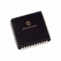
PIC18F442-I/L Microchip Technology, PIC18F442-I/L Datasheet - Page 320

PIC18F442-I/L
Manufacturer Part Number
PIC18F442-I/L
Description
IC MCU FLASH 8KX16 EE A/D 44PLCC
Manufacturer
Microchip Technology
Series
PIC® 18Fr
Datasheets
1.PIC16F616T-ISL.pdf
(8 pages)
2.PIC18F242-ISO.pdf
(332 pages)
3.PIC18F242-ISO.pdf
(14 pages)
4.PIC18F242-ISO.pdf
(16 pages)
5.PIC18F242-ISO.pdf
(16 pages)
6.PIC18F242-ISO.pdf
(14 pages)
7.PIC18LF242-ISO.pdf
(36 pages)
Specifications of PIC18F442-I/L
Core Size
8-Bit
Program Memory Size
16KB (8K x 16)
Core Processor
PIC
Speed
40MHz
Connectivity
I²C, SPI, UART/USART
Peripherals
Brown-out Detect/Reset, LVD, POR, PWM, WDT
Number Of I /o
34
Program Memory Type
FLASH
Eeprom Size
256 x 8
Ram Size
768 x 8
Voltage - Supply (vcc/vdd)
4.2 V ~ 5.5 V
Data Converters
A/D 8x10b
Oscillator Type
External
Operating Temperature
-40°C ~ 85°C
Package / Case
44-PLCC
Controller Family/series
PIC18
No. Of I/o's
34
Eeprom Memory Size
256Byte
Ram Memory Size
768Byte
Cpu Speed
40MHz
No. Of Timers
4
Processor Series
PIC18F
Core
PIC
Data Bus Width
8 bit
Data Ram Size
768 B
Interface Type
MSSP, SPI, I2C, PSP, USART
Maximum Clock Frequency
40 MHz
Number Of Programmable I/os
34
Number Of Timers
1 x 16 bit
Operating Supply Voltage
2 V to 5.5 V
Maximum Operating Temperature
+ 85 C
Mounting Style
SMD/SMT
3rd Party Development Tools
52715-96, 52716-328, 52717-734, 52712-325, EWPIC18
Development Tools By Supplier
PG164130, DV164035, DV244005, DV164005, PG164120, ICE2000, ICE4000, DM163022, DV164136
Minimum Operating Temperature
- 40 C
On-chip Adc
8
Package
44PLCC
Device Core
PIC
Family Name
PIC18
Maximum Speed
40 MHz
Lead Free Status / RoHS Status
Lead free / RoHS Compliant
For Use With
AC164309 - MODULE SKT FOR PM3 44PLCCXLT44L2 - SOCKET TRAN ICE 44PLCC444-1001 - DEMO BOARD FOR PICMICRO MCUDVA16XL441 - ADAPTER DEVICE ICE 44PLCCDV007003 - PROGRAMMER UNIVERSAL PROMATE II
Lead Free Status / Rohs Status
Details
Other names
PIC18F442I/L
Available stocks
Company
Part Number
Manufacturer
Quantity
Price
Company:
Part Number:
PIC18F442-I/L
Manufacturer:
Microchip Technology
Quantity:
10 000
PIC18FXX2
C
CALL ................................................................................ 226
Capture (CCP Module) ..................................................... 119
Capture/Compare/PWM (CCP) ........................................ 117
Clocking Scheme/Instruction Cycle .................................... 39
CLRF ................................................................................ 227
CLRWDT .......................................................................... 227
Code Examples
Code Protection ............................................................... 195
COMF ............................................................................... 228
Compare (CCP Module) ................................................... 120
Configuration Bits ............................................................. 195
Context Saving During Interrupts ....................................... 85
Conversion Considerations .............................................. 314
CPFSEQ .......................................................................... 228
CPFSGT ........................................................................... 229
CPFSLT ........................................................................... 229
DS39564C-page 318
Associated Registers ............................................... 121
CCP Pin Configuration ............................................. 119
CCPR1H:CCPR1L Registers ................................... 119
Software Interrupt ..................................................... 119
Timer1/Timer3 Mode Selection ................................ 119
Capture Mode. See Capture
CCP1 ........................................................................ 118
CCP2 ........................................................................ 118
Compare Mode. See Compare
Interaction of Two CCP Modules ............................. 118
PWM Mode. See PWM
Timer Resources ...................................................... 118
16 x 16 Signed Multiply Routine ................................. 72
16 x 16 Unsigned Multiply Routine ............................. 72
8 x 8 Signed Multiply Routine ..................................... 71
8 x 8 Unsigned Multiply Routine ................................. 71
Changing Between Capture Prescalers ................... 119
Data EEPROM Read ................................................. 67
Data EEPROM Refresh Routine ................................ 68
Data EEPROM Write .................................................. 67
Erasing a FLASH Program Memory Row .................. 60
Fast Register Stack .................................................... 39
How to Clear RAM (Bank1) Using
Initializing PORTA ...................................................... 87
Initializing PORTB ...................................................... 90
Initializing PORTC ...................................................... 93
Initializing PORTD ...................................................... 95
Initializing PORTE ...................................................... 97
Loading the SSPBUF (SSPSR) Register ................. 128
Reading a FLASH Program Memory Word ................ 59
Saving STATUS, WREG and BSR
Writing to FLASH Program Memory ..................... 62–63
Associated Registers ............................................... 121
CCP Pin Configuration ............................................. 120
CCPR1 Register ....................................................... 120
Software Interrupt ..................................................... 120
Special Event Trigger ........................109, 115, 120, 188
Timer1/Timer3 Mode Selection ................................ 120
CCPR1H Register ............................................ 118
CCPR1L Register ............................................ 118
CCPR2H Register ............................................ 118
CCPR2L Register ............................................ 118
Indirect Addressing ............................................ 50
Registers in RAM ............................................... 85
D
Data EEPROM Memory
Data Memory ..................................................................... 42
DAW ................................................................................ 230
DC and AC Characteristics
DC Characteristics ....................................................261, 265
DCFSNZ .......................................................................... 231
DECF ............................................................................... 230
DECFSZ .......................................................................... 231
Development Support ...................................................... 253
Device Differences ........................................................... 313
Device Overview .................................................................. 7
Direct Addressing ............................................................... 51
E
Electrical Characteristics .................................................. 259
Errata ................................................................................... 5
F
Firmware Instructions ....................................................... 211
FLASH Program Memory ................................................... 55
G
General Call Address Support ......................................... 148
GOTO .............................................................................. 232
Associated Registers ................................................. 69
EEADR Register ........................................................ 65
EECON1 Register ...................................................... 65
EECON2 Register ...................................................... 65
Operation During Code Protect ................................. 68
Protection Against Spurious Write ............................. 68
Reading ..................................................................... 67
Using .......................................................................... 68
Write Verify ................................................................ 68
Writing ........................................................................ 67
General Purpose Registers ....................................... 42
Map for PIC18F242/442 ............................................ 43
Map for PIC18F252/452 ............................................ 44
Special Function Registers ........................................ 42
Graphs and Tables .................................................. 289
Features ....................................................................... 7
Example ..................................................................... 49
Associated Registers ................................................. 63
Control Registers ....................................................... 56
Erase Sequence ........................................................ 60
Erasing ....................................................................... 60
Operation During Code Protect ................................. 63
Reading ..................................................................... 59
TABLAT Register ....................................................... 58
Table Pointer ............................................................. 58
Table Pointer Boundaries .......................................... 58
Table Reads and Table Writes .................................. 55
Writing to .................................................................... 61
Boundaries Based on Operation ........................ 58
Block Diagrams
Protection Against Spurious Writes ................... 63
Unexpected Termination .................................... 63
Write Verify ........................................................ 63
Reads from FLASH Program Memory ....... 59
© 2006 Microchip Technology Inc.


