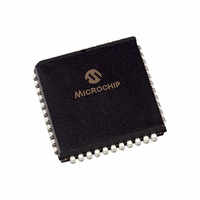
PIC16C74A-20I/L Microchip Technology, PIC16C74A-20I/L Datasheet - Page 46

PIC16C74A-20I/L
Manufacturer Part Number
PIC16C74A-20I/L
Description
IC MCU OTP 4KX14 A/D PWM 44PLCC
Manufacturer
Microchip Technology
Series
PIC® 16Cr
Datasheets
1.PIC16F616T-ISL.pdf
(8 pages)
2.PIC16F818-ISO.pdf
(6 pages)
3.PIC16C72-04SO.pdf
(289 pages)
4.PIC16LC74A-04P.pdf
(8 pages)
Specifications of PIC16C74A-20I/L
Core Size
8-Bit
Program Memory Size
7KB (4K x 14)
Peripherals
Brown-out Detect/Reset, POR, PWM, WDT
Core Processor
PIC
Speed
20MHz
Connectivity
I²C, SPI, UART/USART
Number Of I /o
33
Program Memory Type
OTP
Ram Size
192 x 8
Voltage - Supply (vcc/vdd)
4 V ~ 6 V
Data Converters
A/D 8x8b
Oscillator Type
External
Operating Temperature
-40°C ~ 85°C
Package / Case
44-PLCC
Controller Family/series
PIC16C
No. Of I/o's
33
Ram Memory Size
192Byte
Cpu Speed
20MHz
No. Of Timers
3
Processor Series
PIC16C
Core
PIC
Data Bus Width
8 bit
Data Ram Size
192 B
Interface Type
I2C, SPI, USART
Maximum Clock Frequency
20 MHz
Number Of Programmable I/os
33
Number Of Timers
3
Maximum Operating Temperature
+ 85 C
Mounting Style
SMD/SMT
3rd Party Development Tools
52715-96, 52716-328, 52717-734
Development Tools By Supplier
ICE2000, DM163022
Minimum Operating Temperature
- 40 C
On-chip Adc
8 bit, 8 Channel
Lead Free Status / RoHS Status
Lead free / RoHS Compliant
For Use With
AC164309 - MODULE SKT FOR PM3 44PLCC444-1001 - DEMO BOARD FOR PICMICRO MCUDVA16XL441 - ADAPTER DEVICE ICE 44PLCC309-1040 - ADAPTER 44-PLCC ZIF TO 40-DIP309-1039 - ADAPTER 44-PLCC TO 40-DIPDV007003 - PROGRAMMER UNIVERSAL PROMATE II
Eeprom Size
-
Lead Free Status / Rohs Status
Details
Available stocks
Company
Part Number
Manufacturer
Quantity
Price
Company:
Part Number:
PIC16C74A-20I/L
Manufacturer:
Microchip Technology
Quantity:
10 000
Part Number:
PIC16C74A-20I/L
Manufacturer:
MICCROCHIP
Quantity:
20 000
- PIC16F616T-ISL PDF datasheet
- PIC16F818-ISO PDF datasheet #2
- PIC16C72-04SO PDF datasheet #3
- PIC16LC74A-04P PDF datasheet #4
- Current page: 46 of 289
- Download datasheet (3Mb)
PIC16C7X
FIGURE 5-4:
TABLE 5-3:
DS30390E-page 46
Set RBIF
Name
RB0/INT
RB1
RB2
RB3
RB4
RB5
RB6
RB7
Legend: TTL = TTL input, ST = Schmitt Trigger input
Note 1: This buffer is a Schmitt Trigger input when configured as the external interrupt.
Data bus
Note 1: I/O pins have diode protection to V
WR TRIS
WR Port
RBPU
RB7:RB6 in serial programming mode
2: This buffer is a Schmitt Trigger input when used in serial programming mode.
2: To enable weak pull-ups, set the appropriate TRIS bit(s)
(2)
From other
RB7:RB4 pins
and clear the RBPU bit (OPTION<7>).
Bit#
bit0
bit1
bit2
bit3
bit4
bit5
bit6
bit7
BLOCK DIAGRAM OF
RB7:RB4 PINS (PIC16C73/74)
PORTB FUNCTIONS
RD TRIS
RD Port
Data Latch
TRIS Latch
D
D
CK
CK
Q
Q
TTL/ST
TTL/ST
TTL/ST
Buffer
TTL
TTL
TTL
TTL
TTL
Q
Q
Latch
(1)
(2)
(2)
DD
EN
EN
D
and V
D
TTL
Input
Buffer
Input/output pin or external interrupt input. Internal software
programmable weak pull-up.
Input/output pin. Internal software programmable weak pull-up.
Input/output pin. Internal software programmable weak pull-up.
Input/output pin. Internal software programmable weak pull-up.
Input/output pin (with interrupt on change). Internal software programmable
weak pull-up.
Input/output pin (with interrupt on change). Internal software programmable
weak pull-up.
Input/output pin (with interrupt on change). Internal software programmable
weak pull-up. Serial programming clock.
Input/output pin (with interrupt on change). Internal software programmable
weak pull-up. Serial programming data.
Function
SS
V
RD Port
P
.
DD
Buffer
weak
pull-up
I/O
pin
ST
(1)
FIGURE 5-5:
Data bus
WR Port
WR TRIS
RBPU
Note 1: I/O pins have diode protection to V
RB7:RB6 in serial programming mode
Set RBIF
From other
RB7:RB4 pins
2: To enable weak pull-ups, set the appropriate TRIS bit(s)
(2)
and clear the RBPU bit (OPTION<7>).
RD TRIS
RD Port
Data Latch
TRIS Latch
D
D
BLOCK DIAGRAM OF
RB7:RB4 PINS (PIC16C72/
73A/74A/76/77)
CK
CK
Q
Q
1997 Microchip Technology Inc.
Q
Q
Latch
DD
EN
EN
D
D
and V
TTL
Input
Buffer
SS
V
P
DD
.
weak
pull-up
RD Port
Buffer
I/O
pin
Q1
Q3
(1)
ST
Related parts for PIC16C74A-20I/L
Image
Part Number
Description
Manufacturer
Datasheet
Request
R

Part Number:
Description:
IC MCU OTP 4KX14 A/D PWM 44PLCC
Manufacturer:
Microchip Technology
Datasheet:

Part Number:
Description:
IC,MICROCONTROLLER,8-BIT,PIC CPU,CMOS,LDCC,44PIN,PLASTIC
Manufacturer:
Microchip Technology
Datasheet:

Part Number:
Description:
IC MCU OTP 4KX14 A/D PWM 44PLCC
Manufacturer:
Microchip Technology
Datasheet:

Part Number:
Description:
IC MCU OTP 4KX14 A/D PWM 40DIP
Manufacturer:
Microchip Technology
Datasheet:

Part Number:
Description:
IC MCU OTP 4KX14 A/D PWM 44PLCC
Manufacturer:
Microchip Technology
Datasheet:

Part Number:
Description:
IC MCU OTP 4KX14 A/D PWM 44-MQFP
Manufacturer:
Microchip Technology
Datasheet:

Part Number:
Description:
IC MCU OTP 4KX14 A/D PWM 40DIP
Manufacturer:
Microchip Technology
Datasheet:

Part Number:
Description:
IC MCU OTP 4KX14 A/D PWM 40DIP
Manufacturer:
Microchip Technology
Datasheet:

Part Number:
Description:
IC MCU OTP 4KX14 A/D PWM 40DIP
Manufacturer:
Microchip Technology
Datasheet:

Part Number:
Description:
IC MCU OTP 4KX14 A/D PWM 44PLCC
Manufacturer:
Microchip Technology
Datasheet:

Part Number:
Description:
IC MCU OTP 4KX14 A/D PWM 44-MQFP
Manufacturer:
Microchip Technology
Datasheet:

Part Number:
Description:
IC MCU OTP 4KX14 A/D PWM 40DIP
Manufacturer:
Microchip Technology
Datasheet:

Part Number:
Description:
IC MCU OTP 4KX14 A/D PWM 40DIP
Manufacturer:
Microchip Technology
Datasheet:

Part Number:
Description:
IC MCU OTP 4KX14 A/D PWM 44-MQFP
Manufacturer:
Microchip Technology
Datasheet:

Part Number:
Description:
IC MCU OTP 4KX14 A/D PWM 44-MQFP
Manufacturer:
Microchip Technology
Datasheet:


