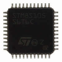
STM8S105S6T6C STMicroelectronics, STM8S105S6T6C Datasheet - Page 98

STM8S105S6T6C
Manufacturer Part Number
STM8S105S6T6C
Description
MCU 32KB FLASH MEM 16MHZ 44-LQFP
Manufacturer
STMicroelectronics
Series
STM8Sr
Datasheet
1.STM8S105C4T6.pdf
(127 pages)
Specifications of STM8S105S6T6C
Core Processor
STM8
Core Size
8-Bit
Speed
16MHz
Connectivity
I²C, IrDA, LIN, SPI, UART/USART
Peripherals
Brown-out Detect/Reset, POR, PWM, WDT
Number Of I /o
34
Program Memory Size
32KB (32K x 8)
Program Memory Type
FLASH
Eeprom Size
1K x 8
Ram Size
2K x 8
Voltage - Supply (vcc/vdd)
2.95 V ~ 5.5 V
Data Converters
A/D 9x10b
Oscillator Type
Internal
Operating Temperature
-40°C ~ 85°C
Package / Case
44-LQFP
Processor Series
STM8S10x
Core
STM8
Data Bus Width
8 bit
Data Ram Size
2 KB
Interface Type
I2C, SPI, UART
Maximum Clock Frequency
16 MHz
Number Of Programmable I/os
34
Number Of Timers
8
Maximum Operating Temperature
+ 85 C
Mounting Style
SMD/SMT
3rd Party Development Tools
EWSTM8
Development Tools By Supplier
STICE-SYS001
Minimum Operating Temperature
- 40 C
On-chip Adc
10 bit, 9 Channel
For Use With
497-10040 - EVAL KIT STM8S DISCOVERY497-10593 - KIT STARTER FOR STM8S207/8 SER
Lead Free Status / RoHS Status
Lead free / RoHS Compliant
Other names
497-8949
STM8S105S6T6C
STM8S105S6T6C
Available stocks
Company
Part Number
Manufacturer
Quantity
Price
Company:
Part Number:
STM8S105S6T6C
Manufacturer:
STMicroelectronics
Quantity:
10 000
Part Number:
STM8S105S6T6C
Manufacturer:
ST
Quantity:
20 000
Electrical characteristics
98/127
Symbol
changes of the analog input voltage have no effect on the conversion result. Values for the
sample clock t
|E
|E
|E
|E
|E
(1)
(2)
analog input pins should be avoided as this significantly reduces the accuracy of the
conversion being performed on another analog input. It is recommended to add a Schottky
diode (pin to ground) to standard analog pins which may potentially inject negative current.
T
O
G
D
L
Data based on characterisation results, not tested in production.
ADC accuracy vs. negative injection current: Injecting negative current on any of the
|
|
|
|
|
Parameter
Total unadjusted error
Offset error
Gain error
Differential linearity error
Integral linearity error
S
depend on programming.
Table 46: ADC accuracy with R
(2)
(2)
DocID14771 Rev 10
(2)
(2)
(2)
Conditions
f
f
f
f
f
f
f
f
f
f
f
f
f
f
f
ADC
ADC
ADC
ADC
ADC
ADC
ADC
ADC
ADC
ADC
ADC
ADC
ADC
ADC
ADC
= 2 MHz
= 4 MHz
= 6 MHz
= 2 MHz
= 4 MHz
= 6 MHz
= 2 MHz
= 4 MHz
= 6 MHz
= 2 MHz
= 4 MHz
= 6 MHz
= 2 MHz
= 4 MHz
= 6 MHz
AIN
< 10 kΩ , V
DDA
Typ
1.0
1.4
1.6
0.6
1.1
1.2
0.2
0.6
0.8
0.7
0.7
0.8
0.6
0.6
0.6
= 5 V
Max
2.5
3.0
3.5
2.0
2.5
2.5
2.0
2.5
2.5
1.5
1.5
1.5
1.5
1.5
1.5
STM8S105xx
(1)
Unit
LSB


