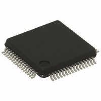
STM32F103RBT6 STMicroelectronics, STM32F103RBT6 Datasheet - Page 39

STM32F103RBT6
Manufacturer Part Number
STM32F103RBT6
Description
MCU ARM 128KB FLASH MEM 64-LQFP
Manufacturer
STMicroelectronics
Series
STM32r
Datasheet
1.STM32F103R8T6.pdf
(96 pages)
Specifications of STM32F103RBT6
Core Processor
ARM® Cortex-M3™
Core Size
32-Bit
Speed
72MHz
Connectivity
CAN, I²C, IrDA, LIN, SPI, UART/USART, USB
Peripherals
DMA, Motor Control PWM, PDR, POR, PVD, PWM, Temp Sensor, WDT
Number Of I /o
51
Program Memory Size
128KB (128K x 8)
Program Memory Type
FLASH
Ram Size
20K x 8
Voltage - Supply (vcc/vdd)
2 V ~ 3.6 V
Data Converters
A/D 16x12b
Oscillator Type
Internal
Operating Temperature
-40°C ~ 85°C
Package / Case
64-LQFP
Processor Series
STM32F103x
Core
ARM Cortex M3
Data Bus Width
32 bit
Data Ram Size
20 KB
Interface Type
CAN/I2C/SPI/USART/USB
Maximum Clock Frequency
72 MHz
Number Of Programmable I/os
51
Number Of Timers
4
Operating Supply Voltage
2 V to 3.6 V
Maximum Operating Temperature
+ 85 C
Mounting Style
SMD/SMT
3rd Party Development Tools
EWARM, EWARM-BL, KSDK-STM32-PLUS, KSK-STM32-JL, MDK-ARM, RL-ARM, ULINK2
Development Tools By Supplier
ST-LINK
Minimum Operating Temperature
- 40 C
On-chip Adc
2 (16-ch x 12-bit)
Cpu Family
STM32
Device Core
ARM Cortex-M3
Device Core Size
32b
Frequency (max)
72MHz
Total Internal Ram Size
20KB
# I/os (max)
51
Number Of Timers - General Purpose
4
Operating Supply Voltage (typ)
2.5/3.3V
Operating Supply Voltage (max)
3.6V
Operating Supply Voltage (min)
2V
Instruction Set Architecture
RISC
Operating Temp Range
-40C to 85C
Operating Temperature Classification
Industrial
Mounting
Surface Mount
Pin Count
64
Package Type
LQFP
For Use With
497-10841 - INTERFACE BOARD BASED ON STM32X497-10048 - BOARD EVAL ACCELEROMETER497-10030 - STARTER KIT FOR STM32497-8853 - BOARD DEMO STM32 UNIV USB-UUSCIKSDKSTM32-PL - KIT IAR KICKSTART STM32 CORTEXM3497-8512 - KIT STARTER FOR STM32F10XE MCU497-8511 - KIT STARTER FOR STM32 512K FLASH497-8505 - KIT STARTER FOR STM32F10XE MCU497-8418 - BOARD DEMO DGTL PHOTOFRAME STM32497-8304 - KIT STM32 MOTOR DRIVER BLDC497-6438 - BOARD EVALUTION FOR STM32 512K497-6289 - KIT PERFORMANCE STICK FOR STM32MCBSTM32UME - BOARD EVAL MCBSTM32 + ULINK-MEMCBSTM32U - BOARD EVAL MCBSTM32 + ULINK2MCBSTM32 - BOARD EVAL FOR STM STM32X SER497-6053 - KIT STARTER FOR STM32497-6052 - KIT STARTER FOR STM32497-6050 - KIT STARTER FOR STM32497-6049 - KIT EVALUATION LOW COST STM32497-6048 - BOARD EVALUATION FOR STM32497-6047 - KIT DEVELOPMENT FOR STM32497-5046 - KIT TOOL FOR ST7/UPSD/STR7 MCU
Lead Free Status / RoHS Status
Lead free / RoHS Compliant
Eeprom Size
-
Lead Free Status / Rohs Status
Lead free / RoHS Compliant
Other names
497-6066
Available stocks
Company
Part Number
Manufacturer
Quantity
Price
Company:
Part Number:
STM32F103RBT6
Manufacturer:
STMicroelectronics
Quantity:
4 750
Company:
Part Number:
STM32F103RBT6
Manufacturer:
STMicroelectronics
Quantity:
10 000
Part Number:
STM32F103RBT6
Manufacturer:
ST
Quantity:
20 000
Company:
Part Number:
STM32F103RBT6TR
Manufacturer:
DELTA
Quantity:
1 000
Company:
Part Number:
STM32F103RBT6TR
Manufacturer:
ST
Quantity:
20
STM32F103x8, STM32F103xB
5.3.4
5.3.5
Embedded reference voltage
The parameters given in
temperature and V
Table 12.
1. Shortest sampling time can be determined in the application by multiple iterations.
2. Guaranteed by design, not tested in production.
Supply current characteristics
The current consumption is a function of several parameters and factors such as the
operating voltage, ambient temperature, I/O pin loading, device software configuration,
operating frequencies, I/O pin switching rate, program location in memory and executed
binary code.
The current consumption is measured as described in
measurement
All Run-mode current consumption measurements given in this section are performed with a
reduced code that gives a consumption equivalent to Dhrystone 2.1 code.
Maximum current consumption
The MCU is placed under the following conditions:
●
●
●
●
●
The parameters given in
under ambient temperature and V
T
V
Symbol
V
S_vrefint
T
RERINT
REFINT
Coeff
All I/O pins are in input mode with a static value at V
All peripherals are disabled except when explicitly mentioned
The Flash memory access time is adjusted to the f
to 24 MHz, 1 wait state from 24 to 48 MHz and 2 wait states above)
Prefetch in ON (reminder: this bit must be set before clock setting and bus prescaling)
When the peripherals are enabled f
(2)
(2)
(1)
Internal reference voltage
ADC sampling time when
reading the internal reference
voltage
Internal reference voltage
spread over the temperature
range
Temperature coefficient
Embedded internal reference voltage
scheme.
DD
Parameter
supply voltage conditions summarized in
Table 12
Table
Doc ID 13587 Rev 12
13,
DD
are derived from tests performed under ambient
Table 14
supply voltage conditions summarized in
PCLK1
–40 °C < T
–40 °C < T
V
and
DD
Conditions
= f
= 3 V ±10 mV
Table 15
HCLK
A
A
< +105 °C
< +85 °C
/2, f
Figure 14: Current consumption
HCLK
DD
are derived from tests performed
PCLK2
or V
frequency (0 wait state from 0
Table
1.16
1.16
Min
= f
SS
Electrical characteristics
HCLK
(no load)
9.
1.20
1.20
Typ
5.1
17.1
1.26
1.24
Max
100
10
Table
(2)
ppm/°C
9.
Unit
mV
µs
V
V
39/96


