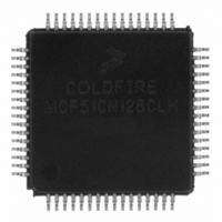
MCF51CN128CLH Freescale Semiconductor, MCF51CN128CLH Datasheet - Page 12

MCF51CN128CLH
Manufacturer Part Number
MCF51CN128CLH
Description
IC MCU 32BIT 128K FLASH 64-LQFP
Manufacturer
Freescale Semiconductor
Series
MCF51CNr
Specifications of MCF51CN128CLH
Core Processor
Coldfire V1
Core Size
32-Bit
Speed
50MHz
Connectivity
Ethernet, I²C, SCI, SPI
Peripherals
LVD, PWM, WDT
Number Of I /o
54
Program Memory Size
128KB (128K x 8)
Program Memory Type
FLASH
Ram Size
24K x 8
Voltage - Supply (vcc/vdd)
1.8 V ~ 3.6 V
Data Converters
A/D 12x12b
Oscillator Type
External
Operating Temperature
-40°C ~ 85°C
Package / Case
64-LQFP
Processor Series
MCF51CN
Core
ColdFire V1
Data Bus Width
32 bit
Data Ram Size
24 KB
Interface Type
I2C, SPI, SCI
Maximum Clock Frequency
25 MHz
Number Of Programmable I/os
54
Operating Supply Voltage
1.8 V to 3.6 V
Maximum Operating Temperature
+ 85 C
Mounting Style
SMD/SMT
3rd Party Development Tools
JLINK-CF-BDM26, EWCF
Development Tools By Supplier
TWR-MCF51CN-KIT, TWR-SER, TWR-ELEV, TOWER
Minimum Operating Temperature
- 40 C
On-chip Adc
12 bit, 12 Channel
Package
64LQFP
Device Core
ColdFire
Family Name
MCF51CN
Maximum Speed
50.33 MHz
Number Of Timers
2
For Use With
TWR-MCF51CN - KIT TOWER BOARDTWR-MCF51CN-KIT - KIT TOWER BOARD/SERIAL/ELEVATOR
Lead Free Status / RoHS Status
Lead free / RoHS Compliant
Eeprom Size
-
Lead Free Status / Rohs Status
Lead free / RoHS Compliant
Available stocks
Company
Part Number
Manufacturer
Quantity
Price
Company:
Part Number:
MCF51CN128CLH
Manufacturer:
Freescale Semiconductor
Quantity:
10 000
Part Number:
MCF51CN128CLH-1M72P
Manufacturer:
FREESCALE
Quantity:
20 000
Introduction to the Serial-to-Ethernet Bridge Software
However, at continuous transfers, either baud rate, transfers can quickly fill the UART software buffer if
they are not taken by the serial bridge application at the same rate. Then the “extra” received at this point
will be dropped. Baud rate and amount of data needed to calculate buffer’s high watermark are highly
dependent on the tasks being run and tasks’ priorities when using an RTOS. This will be explained in the
next section.
For SPI, no flow control is implemented to avoid altering an SPI message with an extra header. Flow
control must be implemented at the application layer by using acknowledges or another customized
flow-control protocol.
Figure 10. How Flow Control Must be Implemented for the SPI Interface at Upper Software Layers
Figure 11. A Hypothetical SPI Packet Using Flow Control
3.2
Buffer Information Between Interfaces
Even if we can stop communication very easily with a flow-control protocol, if we do it very often,
communication performance will go down, especially for serial protocols like UART and SPI.
This performance issue can be easily predicted by using UART or SPI hardware buffers, which are
one-to-four bytes buffers long most of the time. In this hypothetical case, the Ethernet data length can go
from 64 to 1518 bytes (this can be limited by TCP maximum length packet). Data will be sent as soon as
possible to the UART controller, but its hardware buffer will be filled very quickly. Delays can be solved
by using an interrupt-to-signal application bridge that a character can be sent. However, the delay until an
interrupt requesting free space on UART hardware buffer happens must be considered. This delay can be
decreased by using a software buffer between the bridge application and the UART controller. In this way,
the application bridge can fill the software buffer and the UART ISR will take it character by character
until it is emptied in this transmission case. In this way, the number of times communication is stopped by
using flow control is reduced. See
Figure 12
and
Figure 13
for more details.
Serial-to-Ethernet Bridge Using MCF51CN Family and FreeRTOS, Rev. 0
12
Freescale Semiconductor


