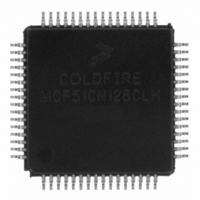
MCF51CN128CLH Freescale Semiconductor, MCF51CN128CLH Datasheet - Page 13

MCF51CN128CLH
Manufacturer Part Number
MCF51CN128CLH
Description
IC MCU 32BIT 128K FLASH 64-LQFP
Manufacturer
Freescale Semiconductor
Series
MCF51CNr
Specifications of MCF51CN128CLH
Core Processor
Coldfire V1
Core Size
32-Bit
Speed
50MHz
Connectivity
Ethernet, I²C, SCI, SPI
Peripherals
LVD, PWM, WDT
Number Of I /o
54
Program Memory Size
128KB (128K x 8)
Program Memory Type
FLASH
Ram Size
24K x 8
Voltage - Supply (vcc/vdd)
1.8 V ~ 3.6 V
Data Converters
A/D 12x12b
Oscillator Type
External
Operating Temperature
-40°C ~ 85°C
Package / Case
64-LQFP
Processor Series
MCF51CN
Core
ColdFire V1
Data Bus Width
32 bit
Data Ram Size
24 KB
Interface Type
I2C, SPI, SCI
Maximum Clock Frequency
25 MHz
Number Of Programmable I/os
54
Operating Supply Voltage
1.8 V to 3.6 V
Maximum Operating Temperature
+ 85 C
Mounting Style
SMD/SMT
3rd Party Development Tools
JLINK-CF-BDM26, EWCF
Development Tools By Supplier
TWR-MCF51CN-KIT, TWR-SER, TWR-ELEV, TOWER
Minimum Operating Temperature
- 40 C
On-chip Adc
12 bit, 12 Channel
Package
64LQFP
Device Core
ColdFire
Family Name
MCF51CN
Maximum Speed
50.33 MHz
Number Of Timers
2
For Use With
TWR-MCF51CN - KIT TOWER BOARDTWR-MCF51CN-KIT - KIT TOWER BOARD/SERIAL/ELEVATOR
Lead Free Status / RoHS Status
Lead free / RoHS Compliant
Eeprom Size
-
Lead Free Status / Rohs Status
Lead free / RoHS Compliant
Available stocks
Company
Part Number
Manufacturer
Quantity
Price
Company:
Part Number:
MCF51CN128CLH
Manufacturer:
Freescale Semiconductor
Quantity:
10 000
Part Number:
MCF51CN128CLH-1M72P
Manufacturer:
FREESCALE
Quantity:
20 000
Introduction to the Serial-to-Ethernet Bridge Software
Figure 12. Bridge without Software Buffer Implementation
Figure 13. Bridge with Software Buffer Implementation
For the UART Rx case, software buffer is important to store all characters that can be received in one
RTOS tick starting to count from the first character and send a more efficient Ethernet packet by using all
the available max bytes for a packet instead of a few bytes. Ethernet is more efficient by using as much
data as possible to avoid an Ethernet header bigger than the data (protocol overhead). This is useful when
a lot of data is to be sent.
The serial bridge solves this problem by using software memory spaces known as buffers in a FIFO
fashion-way to queue and de-queue data. We use independent buffers for Rx and Tx as a way to store all
the information that can’t be processed at the time by the bridge. For the UART software, Tx buffer length
is 512 bytes, which matches with the half of TCP max packet and the half for Rx buffer length. 16 bytes
is used for each SPI software buffer: Tx and Rx.
3.3
Communication Processing
Media access controllers (MACs) or Ethernet controllers have a default buffer implementation, which
means the received data is stored as complete buffers that are managed by a higher Ethernet software
implementation like a TCP/IP stack. In this way, hardware receives the packet as a complete array of bytes
instead of byte per byte, getting a higher communication performance. These buffers’ lengths are usually
fixed to maximal Ethernet packet, which is 1536 bytes. In this implementation, interrupt processing for
each packet seems better than a polling implementation that wastes time waiting for a reception flag to be
set. However, protocols like UART and SPI receive character per character.
Serial-to-Ethernet Bridge Using MCF51CN Family and FreeRTOS, Rev. 0
Freescale Semiconductor
13


