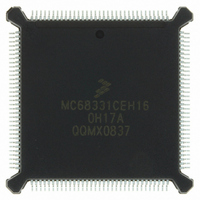
MC68331CEH16 Freescale Semiconductor, MC68331CEH16 Datasheet - Page 39

MC68331CEH16
Manufacturer Part Number
MC68331CEH16
Description
IC MCU 32BIT 16MHZ 132-PQFP
Manufacturer
Freescale Semiconductor
Series
M683xxr
Specifications of MC68331CEH16
Core Processor
CPU32
Core Size
32-Bit
Speed
16MHz
Connectivity
EBI/EMI, SCI, SPI, UART/USART
Peripherals
POR, PWM, WDT
Number Of I /o
18
Program Memory Type
ROMless
Voltage - Supply (vcc/vdd)
4.5 V ~ 5.5 V
Oscillator Type
Internal
Operating Temperature
-40°C ~ 85°C
Package / Case
132-QFP
Package
132PQFP
Device Core
ColdFire
Family Name
68K/M683xx
Maximum Speed
16 MHz
Ram Size
80 Byte
Data Bus Width
32 Bit
Number Of Programmable I/os
18
Interface Type
QSPI/SCI/UART
Number Of Timers
1
Processor Series
M683xx
Core
CPU32
Eeprom Memory
0 Bytes
Input Output
18
Interface
EBI/EMI, SCI, SPI, UART/USART
Ios
18
Memory Type
ROMless
Number Of Bits
32
Package Type
132-pin QFP
Programmable Memory
0 Bytes
Voltage, Range
4.5-5.5 V
Controller Family/series
68K
No. Of I/o's
18
Cpu Speed
16MHz
No. Of Timers
1
Embedded Interface Type
QSPI, SCI, UART
No. Of Pwm Channels
2
Digital Ic Case Style
PQFP
Rohs Compliant
Yes
Data Ram Size
80 B
Maximum Clock Frequency
16 MHz
Maximum Operating Temperature
+ 85 C
Mounting Style
SMD/SMT
Minimum Operating Temperature
- 40 C
Lead Free Status / RoHS Status
Lead free / RoHS Compliant
Eeprom Size
-
Ram Size
-
Program Memory Size
-
Data Converters
-
Lead Free Status / Rohs Status
Lead free / RoHS Compliant
Available stocks
Company
Part Number
Manufacturer
Quantity
Price
Company:
Part Number:
MC68331CEH16
Manufacturer:
Freescale Semiconductor
Quantity:
10 000
Part Number:
MC68331CEH16
Manufacturer:
FREESCALE
Quantity:
20 000
3.7.5 Use of Three State Control Pin
3.8 Interrupts
MC68331TS/D
The SIM clock synthesizer provides clock signals to the other MCU modules. After the clock is running
and the internal reset signal is asserted for four clock cycles, these modules reset. V
VCO frequency ramp time determine how long these four cycles take. Worst case is approximately 15
milliseconds. During this period, module port pins may be in an indeterminate state. While input-only
pins can be put in a known state by means of external pull-up resistors, external logic on input/output
or output-only pins must condition the lines during this time. Active drivers require high-impedance buff-
ers or isolation resistors to prevent conflict.
Asserting the three-state control (TSC) input causes the MCU to put all output drivers in an inactive,
high-impedance state. The signal must remain asserted for 10 clock cycles in order for drivers to
change state. There are certain constraints on use of TSC during power-on reset:
Interrupt recognition and servicing involve complex interaction between the central processing unit, the
system integration module, and a device or module requesting interrupt service.
The CPU32 provides for eight levels of interrupt priority (0–7), seven automatic interrupt vectors and
200 assignable interrupt vector. All interrupts with priorities less than 7 can be masked by the interrupt
priority (IP) field in the status register. The CPU32 handles interrupts as a type of asynchronous excep-
tion.
Interrupt recognition is based on the states of interrupt request signals IRQ[7:1] and the IP mask value.
Each of the signals corresponds to an interrupt priority. IRQ1 has the lowest priority, and IRQ7 has the
highest priority.
The IP field consists of three bits. Binary values %000 to %111 provide eight priority masks. Masks pre-
vent an interrupt request of a priority less than or equal to the mask value (except for IRQ7) from being
recognized and processed. When IP contains %000, no interrupt is masked. During exception process-
ing, the IP field is set to the priority of the interrupt being serviced.
Interrupt request signals can be asserted by external devices or by microcontroller modules. Request
lines are connected internally by means of a wired NOR — simultaneous requests of differing priority
can be made. Internal assertion of an interrupt request signal does not affect the logic state of the cor-
responding MCU pin.
External interrupt requests are routed to the CPU via the external bus interface and SIM interrupt control
logic. The CPU treats external interrupt requests as though they come from the SIM.
External IRQ[6:1] are active-low level-sensitive inputs. External IRQ7 is an active-low transition-sensi-
tive input. IRQ7 requires both an edge and a voltage level for validity.
IRQ[6:1] are maskable. IRQ7 is nonmaskable. The IRQ7 input is transition-sensitive in order to prevent
redundant servicing and stack overflow. A nonmaskable interrupt is generated each time IRQ7 is as-
serted, and each time the priority mask changes from %111 to a lower number while IRQ7 is asserted.
When the internal clock synthesizer is used (MODCLK held high during reset), synthesizer ramp-
up time affects how long the 10 cycles take. Worst case is approximately 20 milliseconds from TSC
assertion.
When an external clock signal is applied (MODCLK held low during reset), pins go to high-imped-
ance state as soon after TSC assertion as 10 clock pulses have been applied to the EXTAL pin.
When TSC assertion takes effect, internal signals are forced to values that can cause inadvertent
mode selection. Once the output drivers change state, the MCU must be powered down and re-
started before normal operation can resume.
Freescale Semiconductor, Inc.
For More Information On This Product,
Go to: www.freescale.com
DD
ramp time and
39


