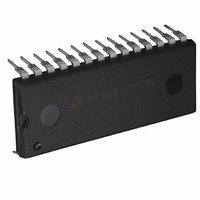
MC908JL16CPE Freescale Semiconductor, MC908JL16CPE Datasheet - Page 64

MC908JL16CPE
Manufacturer Part Number
MC908JL16CPE
Description
IC MCU 16K FLASH 8MHZ 28-DIP
Manufacturer
Freescale Semiconductor
Series
HC08r
Datasheet
1.MC908JL16CFJER.pdf
(230 pages)
Specifications of MC908JL16CPE
Core Processor
HC08
Core Size
8-Bit
Speed
8MHz
Connectivity
I²C, SCI
Peripherals
LED, LVD, POR, PWM
Number Of I /o
23
Program Memory Size
16KB (16K x 8)
Program Memory Type
FLASH
Ram Size
512 x 8
Voltage - Supply (vcc/vdd)
2.7 V ~ 5.5 V
Data Converters
A/D 12x10b
Oscillator Type
Internal
Operating Temperature
-40°C ~ 85°C
Package / Case
28-DIP (0.600", 15.24mm)
Controller Family/series
HC08
No. Of I/o's
23
Ram Memory Size
512Byte
Cpu Speed
8MHz
No. Of Timers
2
Embedded Interface Type
I2C, SCI
Rohs Compliant
Yes
Processor Series
HC08JL
Core
HC08
Data Bus Width
8 bit
Data Ram Size
512 B
Interface Type
SCI
Maximum Clock Frequency
16 MHz
Number Of Programmable I/os
23
Number Of Timers
4
Operating Supply Voltage
2.7 V to 5.5 V
Maximum Operating Temperature
+ 85 C
Mounting Style
Through Hole
Development Tools By Supplier
FSICEBASE, DEMO908JL16E, M68CBL05CE
Minimum Operating Temperature
- 40 C
On-chip Adc
10 bit, 12 Channel
For Use With
DEMO908JL16E - BOARD DEMO FOR MC908JL16
Lead Free Status / RoHS Status
Lead free / RoHS Compliant
Eeprom Size
-
Lead Free Status / Rohs Status
Details
Available stocks
Company
Part Number
Manufacturer
Quantity
Price
Company:
Part Number:
MC908JL16CPE
Manufacturer:
AMS
Quantity:
183
Part Number:
MC908JL16CPE
Manufacturer:
FREESCALE
Quantity:
20 000
- Current page: 64 of 230
- Download datasheet (2Mb)
Oscillator (OSC)
OSCSEL — Oscillator Select Bit
Bits 6–0 — Should be left as logic 1’s.
5.2.1 XTAL Oscillator
The XTAL oscillator circuit is designed for use with an external crystal or ceramic resonator to provide
accurate clock source.
In its typical configuration, the XTAL oscillator is connected in a Pierce oscillator configuration, as shown
in
represent actual circuitry. The oscillator configuration uses five components:
The series resistor (R
be required for all ranges of operation, especially with high frequency crystals. Refer to the crystal
manufacturer’s data for more information.
5.2.2 RC Oscillator
The RC oscillator circuit is designed for use with external resistor and capacitor to provide a clock source
with tolerance less than 10%. See
In its typical configuration, the RC oscillator requires two external components, one R and one C.
Component values should have a tolerance of 1% or less, to obtain a clock source with less than 10%
tolerance. The oscillator configuration uses two components:
64
Figure
OSCSEL selects the oscillator type for the MCU. The erased or unprogrammed state of this bit is
logic 1, selecting the crystal oscillator option. This bit is unaffected by reset.
•
•
•
•
•
•
•
1 = Crystal oscillator
0 = RC oscillator
Crystal, X
Fixed capacitor, C
Tuning capacitor, C
Feedback resistor, R
Series resistor, R
C
R
EXT
EXT
5-2. This figure shows only the logical representation of the internal components and may not
Non-volatile FLASH register; write by programming.
Address:
When Crystal oscillator is selected, the OSC2/RCCLK/PTA6/KBI6 pin is
used as OSC2; other functions such as PTA6/KBI6 will not be available.
Erased:
Reset:
Read:
Write:
1
S
OSCSEL
) is included in the diagram to follow strict Pierce oscillator guidelines and may not
$FFD0
Bit 7
S
R
1
1
(optional)
2
B
(can also be a fixed capacitor)
Figure 5-1. Mask Option Register (MOR)
= Reserved
R
6
1
Figure
MC68HC908JL16 Data Sheet, Rev. 1.1
5-3.
R
5
1
NOTE
Unaffected by reset
R
4
1
R
3
1
R
2
1
R
1
1
Freescale Semiconductor
Bit 0
R
1
Related parts for MC908JL16CPE
Image
Part Number
Description
Manufacturer
Datasheet
Request
R
Part Number:
Description:
Manufacturer:
Freescale Semiconductor, Inc
Datasheet:
Part Number:
Description:
Manufacturer:
Freescale Semiconductor, Inc
Datasheet:
Part Number:
Description:
Manufacturer:
Freescale Semiconductor, Inc
Datasheet:
Part Number:
Description:
Manufacturer:
Freescale Semiconductor, Inc
Datasheet:
Part Number:
Description:
Manufacturer:
Freescale Semiconductor, Inc
Datasheet:
Part Number:
Description:
Manufacturer:
Freescale Semiconductor, Inc
Datasheet:
Part Number:
Description:
Manufacturer:
Freescale Semiconductor, Inc
Datasheet:
Part Number:
Description:
Manufacturer:
Freescale Semiconductor, Inc
Datasheet:
Part Number:
Description:
Manufacturer:
Freescale Semiconductor, Inc
Datasheet:
Part Number:
Description:
Manufacturer:
Freescale Semiconductor, Inc
Datasheet:
Part Number:
Description:
Manufacturer:
Freescale Semiconductor, Inc
Datasheet:
Part Number:
Description:
Manufacturer:
Freescale Semiconductor, Inc
Datasheet:
Part Number:
Description:
Manufacturer:
Freescale Semiconductor, Inc
Datasheet:
Part Number:
Description:
Manufacturer:
Freescale Semiconductor, Inc
Datasheet:
Part Number:
Description:
Manufacturer:
Freescale Semiconductor, Inc
Datasheet:


