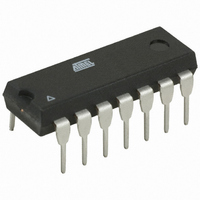
AT89LP214-20PU Atmel, AT89LP214-20PU Datasheet - Page 96

AT89LP214-20PU
Manufacturer Part Number
AT89LP214-20PU
Description
MCU 8051 2K FLASH 20MHZ 14-PDIP
Manufacturer
Atmel
Series
89LPr
Datasheet
1.AT89LP213-20PU.pdf
(98 pages)
Specifications of AT89LP214-20PU
Core Processor
8051
Core Size
8-Bit
Speed
20MHz
Connectivity
SPI, UART/USART
Peripherals
Brown-out Detect/Reset, POR, PWM, WDT
Number Of I /o
12
Program Memory Size
2KB (2K x 8)
Program Memory Type
FLASH
Ram Size
128 x 8
Voltage - Supply (vcc/vdd)
2.4 V ~ 5.5 V
Oscillator Type
Internal
Operating Temperature
-40°C ~ 85°C
Package / Case
14-DIP (0.300", 7.62mm)
Processor Series
AT89x
Core
8051
Data Bus Width
8 bit
Data Ram Size
128 B
Interface Type
SPI/UART
Maximum Clock Frequency
20 MHz
Number Of Programmable I/os
12
Number Of Timers
2
Operating Supply Voltage
2.4 V to 5 V
Maximum Operating Temperature
+ 85 C
Mounting Style
Through Hole
3rd Party Development Tools
PK51, CA51, A51, ULINK2
Development Tools By Supplier
AT89ISP
Minimum Operating Temperature
- 40 C
Lead Free Status / RoHS Status
Lead free / RoHS Compliant
Eeprom Size
-
Data Converters
-
Lead Free Status / Rohs Status
Lead free / RoHS Compliant
Table of Contents (Continued)
ii
AT89LP213/214
11 Power Saving Modes ............................................................................. 17
12 Interrupts ................................................................................................ 19
13 I/O Ports .................................................................................................. 23
14 Enhanced Timer/Counters .................................................................... 28
15 External Interrupts ................................................................................. 37
16 General-purpose Interrupts .................................................................. 37
17 Serial Interface ....................................................................................... 39
18 Serial Peripheral Interface ..................................................................... 50
19 Analog Comparator ............................................................................... 56
10.5
11.1
11.2
12.1
13.1
13.2
13.3
13.4
13.5
14.1
14.2
14.3
14.4
14.5
17.1
17.2
17.3
17.4
17.5
17.6
17.7
19.1
Software Reset ................................................................................................17
Idle Mode .........................................................................................................17
Power-down Mode ...........................................................................................17
Interrupt Response Time .................................................................................21
Port Configuration ............................................................................................24
Port 1 Analog Functions ..................................................................................26
Port Read-modify-write ....................................................................................27
Ports During Powerdown .................................................................................27
Port Alternate Functions ..................................................................................27
Mode 0 – Variable Width Timer/Counter .........................................................29
Mode 1 – 16-bit Auto-Reload Timer/Counter ...................................................30
Mode 2 – 8-bit Auto-reload Timer/Counter ......................................................30
Mode 3 – 8-bit Split Timer ...............................................................................31
Pulse Width Modulation ...................................................................................33
Multiprocessor Communications .....................................................................39
Baud Rates ......................................................................................................41
More About Mode 0 .........................................................................................42
More About Mode 1 .........................................................................................44
More About Modes 2 and 3 .............................................................................46
Framing Error Detection ..................................................................................49
Automatic Address Recognition ......................................................................49
Comparator Interrupt with Debouncing ............................................................56
3538E–MICRO–11/10


