ATTINY2313A-MMH Atmel, ATTINY2313A-MMH Datasheet - Page 18
ATTINY2313A-MMH
Manufacturer Part Number
ATTINY2313A-MMH
Description
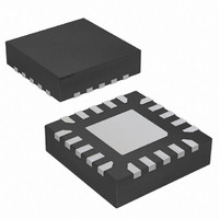
IC MCU AVR 2K FLASH 20QFN
Manufacturer
Atmel
Series
AVR® ATtinyr
Specifications of ATTINY2313A-MMH
Core Processor
AVR
Core Size
8-Bit
Speed
20MHz
Connectivity
I²C, SPI, UART/USART
Peripherals
Brown-out Detect/Reset, POR, PWM, WDT
Number Of I /o
18
Program Memory Size
2KB (1K x 16)
Program Memory Type
FLASH
Eeprom Size
128 x 8
Ram Size
128 x 8
Voltage - Supply (vcc/vdd)
1.8 V ~ 5.5 V
Oscillator Type
Internal
Operating Temperature
-40°C ~ 85°C
Package / Case
20-VQFN Exposed Pad, 20-HVQFN, 20-SQFN, 20-DHVQFN
Processor Series
ATtiny
Core
AVR
Data Bus Width
8 bit
Data Ram Size
128 B
Interface Type
SPI, USART
Maximum Clock Frequency
20 MHz
Number Of Programmable I/os
18
Number Of Timers
2
Operating Supply Voltage
3.3 V
Maximum Operating Temperature
+ 85 C
Mounting Style
SMD/SMT
Minimum Operating Temperature
- 40 C
Operating Temperature Range
- 40 C to + 85 C
Lead Free Status / RoHS Status
Lead free / RoHS Compliant
Data Converters
-
Lead Free Status / Rohs Status
Details
Available stocks
Company
Part Number
Manufacturer
Quantity
Price
Company:

Part Number:
ATTINY2313A-MMH
Manufacturer:
SAMSUNG
Quantity:
101


9. Datasheet Revision History
9.1
18
Rev. 8246A – 11/09
ATtiny2313A/4313
1. Initial revision. Created from document 2543_t2313.
2. Updated datasheet template.
3. Added VQFN in the Pinout
4. Added
5. Added
6. Updated
7. Added
8. Added reset disable function in
9. Added pin change interrupts PCINT1 and PCINT2 in
10. Added PCINT17..8 and PCMSK2..1 in
11. Added
12. Added
13. Updated
14. Updated
15. Updated
16. Added UMSEL1 and UMSEL0 in
17. Added
18. Added USI Buffer Register (USIBR) in
19. Added
20. Updated
21. Updated
22. Added
23. Updated
24. Changed BS to BS1 in
25. Updated
26. Added
27. Updated characteristic plots in
28. Updated
29. Updated
tus Register C” on page
ure 16-1 on page
page
ter” on page
(pages
and the ordering code -MMH (VQFN), and added the topside marking note.
175.
Section 7.2 “Software BOD Disable” on page
Section 7.3 “Power Reduction Register” on page
Section 7.5.3 “BODCR – Brown-Out Detector Control Register” on page
Section 9.3.4 “PCMSK2 – Pin Change Mask Register 2” on page
Section 9.3.5 “PCMSK1 – Pin Change Mask Register 1” on page
Section 15. “USART in SPI Mode” on page
Section 16.5.4 “USIBR – USI Buffer Register” on page
Section 20.3 “Device Signature Imprint Table” on page
Section 22.1 “Effect of Power Reduction” on page
204
Section 19.9.1 “SPMCSR – Store Program Memory Control and Status Regis-
Table 7-2, “Sleep Mode Select,” on page
Section 10.2.1 “Alternate Functions of Port A” on page
Section 10.2.2 “Alternate Functions of Port B” on page
Section 10.2.3 “Alternate Functions of Port D” on page
Section 19.6.3 “Reading Device Signature Imprint Table from Firmware” on
Section 20.3.1 “Calibration Byte” on page
Section 21.2 “DC Characteristics” on page
Section 4. “Register Summary” on page 7
Section 6. “Ordering Information” on page
- 227), and added plots for ATtiny4313 (pages
176.
155.
Section 20.6.13 “Reading the Signature Bytes” on page
139.
Figure 1-1 on page
Section 22. “Typical Characteristics”
Figure 8-1 on page
Section 14.10.4 “UCSRC – USART Control and Sta-
Section 16.2 “Overview” on page 155
Section 9.2 “External Interrupts” on page
2.
36.
145.
181.
38.
.
11, added the package type 20M2
195.
34.
Table 9-1 on page
34.
203.
228
166.
180.
- 251).
61.
62.
66.
for ATtiny2313A
47.
52.
52.
8246AS–AVR–11/09
and in
189.
37.
48.
Fig-
Related parts for ATTINY2313A-MMH
Image
Part Number
Description
Manufacturer
Datasheet
Request
R

Part Number:
Description:
IC, MCU, 8BIT, 2K FLASH, 20SOIC
Manufacturer:
Atmel
Datasheet:

Part Number:
Description:
IC, MCU, 8BIT, 2K FLASH, 20PDIP
Manufacturer:
Atmel
Datasheet:
Part Number:
Description:
IC, MCU, 8BIT, 8K FLASH, 20PDIP
Manufacturer:
Atmel
Datasheet:
Part Number:
Description:
IC, MCU, 8BIT, 8K FLASH, 20SOIC
Manufacturer:
Atmel
Datasheet:

Part Number:
Description:
DEV KIT FOR AVR/AVR32
Manufacturer:
Atmel
Datasheet:

Part Number:
Description:
INTERVAL AND WIPE/WASH WIPER CONTROL IC WITH DELAY
Manufacturer:
ATMEL Corporation
Datasheet:
Part Number:
Description:
Low-Voltage Voice-Switched IC for Hands-Free Operation
Manufacturer:
ATMEL Corporation
Datasheet:
Part Number:
Description:
MONOLITHIC INTEGRATED FEATUREPHONE CIRCUIT
Manufacturer:
ATMEL Corporation
Datasheet:
Part Number:
Description:
AM-FM Receiver IC U4255BM-M
Manufacturer:
ATMEL Corporation
Datasheet:
Part Number:
Description:
Monolithic Integrated Feature Phone Circuit
Manufacturer:
ATMEL Corporation
Datasheet:
Part Number:
Description:
Multistandard Video-IF and Quasi Parallel Sound Processing
Manufacturer:
ATMEL Corporation
Datasheet:
Part Number:
Description:
High-performance EE PLD
Manufacturer:
ATMEL Corporation
Datasheet: