PIC24F04KA201T-I/MQ Microchip Technology, PIC24F04KA201T-I/MQ Datasheet - Page 13
PIC24F04KA201T-I/MQ
Manufacturer Part Number
PIC24F04KA201T-I/MQ
Description
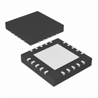
IC PIC MCU FLASH 512KX4 20-QFN
Manufacturer
Microchip Technology
Series
PIC® XLP™ 24Fr
Datasheets
1.PIC24F04KA201-ISS.pdf
(8 pages)
2.PIC24F04KA201-ISS.pdf
(48 pages)
3.PIC24F04KA201-ISS.pdf
(224 pages)
4.PIC24F04KA201-ISS.pdf
(26 pages)
Specifications of PIC24F04KA201T-I/MQ
Program Memory Type
FLASH
Program Memory Size
4KB (1.375K x 24)
Package / Case
20-QFN
Core Processor
PIC
Core Size
16-Bit
Speed
32MHz
Connectivity
I²C, IrDA, SPI, UART/USART
Peripherals
Brown-out Detect/Reset, HLVD, POR, PWM, WDT
Number Of I /o
18
Ram Size
512 x 8
Voltage - Supply (vcc/vdd)
1.8 V ~ 3.6 V
Data Converters
A/D 9x10b
Oscillator Type
Internal
Operating Temperature
-40°C ~ 85°C
Processor Series
PIC24F
Core
PIC
Data Bus Width
16 bit
Data Ram Size
512 B
Interface Type
I2C/SPI/UART
Maximum Clock Frequency
32 MHz
Number Of Programmable I/os
18
Number Of Timers
3
Operating Supply Voltage
1.8 V to 3.6 V
Maximum Operating Temperature
+ 85 C
Mounting Style
SMD/SMT
3rd Party Development Tools
52713-733, 52714-737, 53276-922, EWDSPIC
Development Tools By Supplier
PG164130, DV164035, DV244005, DV164005, DM240001
Minimum Operating Temperature
- 40 C
On-chip Adc
9-ch x 10-bit
Lead Free Status / RoHS Status
Lead free / RoHS Compliant
Eeprom Size
-
Lead Free Status / Rohs Status
Lead free / RoHS Compliant


3.7
The procedure for writing the Configuration registers is
the same as for writing code memory. The only differ-
ence is that only one word is programmed in each
operation. When writing Configuration registers, one
word is programmed during each operation. Only work-
ing register, W0, is used as a temporary holding register
for the data to be programmed.
Table 3-6
Configuration registers.
Table 3-6
programming the Configuration registers, including the
serial pattern with the ICSP command code, which
must be transmitted, LSB first, using the PGCx and
PGDx pins (see
Reset vector is exited. In Step 2, the NVMCON register
is initialized for programming code memory. In Step 3,
the 24-bit starting destination address for programming
is loaded into the TBLPAG register and W7 register.
2010 Microchip Technology Inc.
Note:
Note:
Writing Configuration Registers
provides the ICSP programming details for
provides
The TBLPAG register is hard-coded to
0xF8 (the upper byte address of all
locations of the Configuration registers).
The TBLPAG register must be loaded with
F8h.
Figure
the
3-2). In Step 1 of
default
values
Table
of
3-7, the
the
TABLE 3-6:
FGS
FOSCSEL
FOSC
FWDT
FPOR
FICD
FDS
Note 1:
Configuration
Registers
(1)
PIC24FXXKA2XX
The Configuration register, FICD, is a
reserved location and should be
programmed with the default value given
above.
DEFAULT VALUES FOR
CONFIGURATION REGISTER
SERIAL INSTRUCTION
Value
FFh
DFh
FBh
C3h
FFh
03h
87h
DS39991A-page 13
Related parts for PIC24F04KA201T-I/MQ
Image
Part Number
Description
Manufacturer
Datasheet
Request
R

Part Number:
Description:
Manufacturer:
Microchip Technology Inc.
Datasheet:
Part Number:
Description:
Manufacturer:
Microchip Technology Inc.
Datasheet:
Part Number:
Description:
Manufacturer:
Microchip Technology Inc.
Datasheet:
Part Number:
Description:
Manufacturer:
Microchip Technology Inc.
Datasheet:
Part Number:
Description:
Manufacturer:
Microchip Technology Inc.
Datasheet:
Part Number:
Description:
Manufacturer:
Microchip Technology Inc.
Datasheet:
Part Number:
Description:
Manufacturer:
Microchip Technology Inc.
Datasheet:
Part Number:
Description:
Manufacturer:
Microchip Technology Inc.
Datasheet: