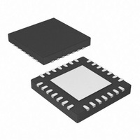
PIC16LF1826-I/MV Microchip Technology, PIC16LF1826-I/MV Datasheet - Page 59

PIC16LF1826-I/MV
Manufacturer Part Number
PIC16LF1826-I/MV
Description
IC MCU 8BIT FLASH 28UQFN
Manufacturer
Microchip Technology
Series
PIC® XLP™ 16Fr
Datasheet
1.PIC16F1826-IP.pdf
(406 pages)
Specifications of PIC16LF1826-I/MV
Core Size
8-Bit
Program Memory Size
3.5KB (2K x 14)
Core Processor
PIC
Speed
32MHz
Connectivity
I²C, SPI, UART/USART
Peripherals
Brown-out Detect/Reset, POR, PWM, WDT
Number Of I /o
16
Program Memory Type
FLASH
Eeprom Size
256 x 8
Ram Size
256 x 8
Voltage - Supply (vcc/vdd)
1.8 V ~ 3.6 V
Data Converters
A/D 12x10b
Oscillator Type
Internal
Operating Temperature
-40°C ~ 85°C
Package / Case
28-UFQFN Exposed Pad
Controller Family/series
PIC16LF
No. Of I/o's
16
Eeprom Memory Size
256Byte
Ram Memory Size
256Byte
Cpu Speed
32MHz
No. Of Timers
3
Processor Series
PIC16LF
Core
PIC
Data Ram Size
256 B
Maximum Clock Frequency
32 KHz
Number Of Programmable I/os
16
Number Of Timers
3
Operating Supply Voltage
1.8 V to 3.6 V
Maximum Operating Temperature
+ 125 C
3rd Party Development Tools
52715-96, 52716-328, 52717-734
Development Tools By Supplier
PG164130, DV164035, DV244005, DV164005
Minimum Operating Temperature
- 40 C
On-chip Adc
10 bit, 12 Channel
On-chip Dac
5 bit
Lead Free Status / RoHS Status
Lead free / RoHS Compliant
Lead Free Status / RoHS Status
Lead free / RoHS Compliant
- Current page: 59 of 406
- Download datasheet (4Mb)
5.2.1.5
The Timer1 Oscillator is a separate crystal oscillator
that is associated with the Timer1 peripheral. It is opti-
mized for timekeeping operations with a 32.768 kHz
crystal connected between the T1OSO and T1OSI
device pins.
The Timer1 Oscillator can be used as an alternate sys-
tem clock source and can be selected during run-time
using clock switching. Refer to Section 5.3 “Clock
Switching” for more information.
FIGURE 5-5:
2010 Microchip Technology Inc.
Note 1: Quartz crystal characteristics vary according
C1
C2
2: Always verify oscillator performance over
3: For oscillator design assistance, reference
• AN826, “Crystal Oscillator Basics and
• AN849, “Basic PIC
• AN943, “Practical PIC
• AN949, “Making Your Oscillator Work”
• TB097, “Interfacing a Micro Crystal
• AN1288, “Design Practices for
to type, package and manufacturer. The
user should consult the manufacturer data
sheets for specifications and recommended
application.
the V
expected for the application.
the following Microchip Applications Notes:
Crystal Selection for rfPIC
Devices” (DS00826)
(DS00849)
Analysis and Design” (DS00943)
(DS00949)
MS1V-T1K 32.768 kHz Tuning Fork
Crystal to a PIC16F690/SS” (DS91097)
Low-Power External Oscillators”
(DS01288)
TIMER1 Oscillator
32.768 kHz
Quartz
Crystal
DD
and temperature range that is
QUARTZ CRYSTAL
OPERATION (TIMER1
OSCILLATOR)
T1OSI
T1OSO
PIC
®
Oscillator Design”
®
®
MCU
Oscillator
®
and PIC
To Internal
Logic
®
Preliminary
5.2.1.6
The external Resistor-Capacitor (RC) modes support
the use of an external RC circuit. This allows the
designer maximum flexibility in frequency choice while
keeping costs to a minimum when clock accuracy is not
required.
The RC circuit connects to OSC1. OSC2/CLKOUT is
available for general purpose I/O or CLKOUT. The
function of the OSC2/CLKOUT pin is determined by the
state of the CLKOUTEN bit in Configuration Word 1.
Figure 5-5 shows the external RC mode connections.
FIGURE 5-6:
The RC oscillator frequency is a function of the supply
voltage, the resistor (R
and the operating temperature. Other factors affecting
the oscillator frequency are:
• threshold voltage variation
• component tolerances
• packaging variations in capacitance
The user also needs to take into account variation due
to tolerance of external RC components used.
F
R
C
OSC
Note 1:
V
Recommended values: 10 k R
EXT
EXT
SS
/4 or
V
DD
PIC16F/LF1826/27
I/O
(1)
Output depends upon CLKOUTEN bit of the
Configuration Word 1.
External RC Mode
OSC1/CLKIN
OSC2/CLKOUT
EXT
EXTERNAL RC MODES
3 k R
C
EXT
) and capacitor (C
PIC
> 20 pF, 2-5V
EXT
®
EXT
MCU
100 k, 3-5V
DS41391C-page 59
100 k, <3V
EXT
Internal
Clock
) values
Related parts for PIC16LF1826-I/MV
Image
Part Number
Description
Manufacturer
Datasheet
Request
R

Part Number:
Description:
IC, 8BIT MCU, PIC16LF, 32MHZ, QFN-28
Manufacturer:
Microchip Technology
Datasheet:

Part Number:
Description:
IC, 8BIT MCU, PIC16LF, 32MHZ, QFN-28
Manufacturer:
Microchip Technology
Datasheet:

Part Number:
Description:
IC, 8BIT MCU, PIC16LF, 32MHZ, DIP-18
Manufacturer:
Microchip Technology
Datasheet:

Part Number:
Description:
IC, 8BIT MCU, PIC16LF, 20MHZ, TQFP-44
Manufacturer:
Microchip Technology
Datasheet:

Part Number:
Description:
7 KB Flash, 384 Bytes RAM, 32 MHz Int. Osc, 16 I/0, Enhanced Mid Range Core, Nan
Manufacturer:
Microchip Technology

Part Number:
Description:
14KB Flash, 512B RAM, LCD, 11x10b ADC, EUSART, NanoWatt XLP 28 SOIC .300in T/R
Manufacturer:
Microchip Technology
Datasheet:

Part Number:
Description:
14KB Flash, 512B RAM, LCD, 11x10b ADC, EUSART, NanoWatt XLP 28 SSOP .209in T/R
Manufacturer:
Microchip Technology
Datasheet:

Part Number:
Description:
MCU PIC 14KB FLASH XLP 28-SSOP
Manufacturer:
Microchip Technology

Part Number:
Description:
MCU PIC 14KB FLASH XLP 28-SOIC
Manufacturer:
Microchip Technology

Part Number:
Description:
MCU PIC 512B FLASH XLP 28-UQFN
Manufacturer:
Microchip Technology

Part Number:
Description:
MCU PIC 14KB FLASH XLP 28-SPDIP
Manufacturer:
Microchip Technology

Part Number:
Description:
MCU 7KB FLASH 256B RAM 40-UQFN
Manufacturer:
Microchip Technology

Part Number:
Description:
MCU 7KB FLASH 256B RAM 44-TQFP
Manufacturer:
Microchip Technology

Part Number:
Description:
MCU 14KB FLASH 1KB RAM 28-UQFN
Manufacturer:
Microchip Technology

Part Number:
Description:
MCU PIC 14KB FLASH XLP 40-UQFN
Manufacturer:
Microchip Technology


