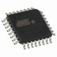
AT89LP828-20AU Atmel, AT89LP828-20AU Datasheet - Page 103

AT89LP828-20AU
Manufacturer Part Number
AT89LP828-20AU
Description
MCU 8051 8K FLASH SPI 32TQFP
Manufacturer
Atmel
Series
89LPr
Datasheet
1.AT89LP428-20AU.pdf
(149 pages)
Specifications of AT89LP828-20AU
Core Processor
8051
Core Size
8-Bit
Speed
20MHz
Connectivity
SPI, UART/USART
Peripherals
Brown-out Detect/Reset, POR, PWM, WDT
Number Of I /o
30
Program Memory Size
8KB (8K x 8)
Program Memory Type
FLASH
Eeprom Size
1K x 8
Ram Size
768 x 8
Voltage - Supply (vcc/vdd)
2.4 V ~ 5.5 V
Oscillator Type
Internal
Operating Temperature
-40°C ~ 85°C
Package / Case
32-TQFP, 32-VQFP
Processor Series
AT89x
Core
8051
Data Bus Width
8 bit
Data Ram Size
768 B
Interface Type
2-Wire, SPI
Maximum Clock Frequency
20 MHz
Number Of Programmable I/os
30
Number Of Timers
3
Maximum Operating Temperature
+ 85 C
Mounting Style
SMD/SMT
3rd Party Development Tools
PK51, CA51, A51, ULINK2
Development Tools By Supplier
AT89ISP
Minimum Operating Temperature
- 40 C
Lead Free Status / RoHS Status
Lead free / RoHS Compliant
Data Converters
-
Lead Free Status / Rohs Status
Details
Available stocks
Company
Part Number
Manufacturer
Quantity
Price
Company:
Part Number:
AT89LP828-20AU
Manufacturer:
Atmel
Quantity:
360
Table 18-2.
Notes:
3654A–MICRO–8/09
Symbol
CSB
[1 - 0]
CONB
CFB
CENB
CMB
[2 - 0]
ACSRB = 9FH
Not Bit Addressable
Bit
1. CONB must be cleared to 0 before changing CSB [1 - 0].
2. Debouncing modes require the use of Timer 1 to generate the sampling delay.
Function
Comparator B Positive Input Channel Select
Comparator B Input Connect. When CONB = 1, the analog input pins are connected to the comparator. When
CONB = 0 the analog input pins are disconnected from the comparator. CONB must be cleared to 0 before changing
CSB [1 - 0] or RFB [1 - 0].
Comparator B Interrupt Flag. Set when the comparator output meets the conditions specified by the CMB [2 - 0] bits and
CENB is set. The flag must be cleared by software. The interrupt may be enabled/disabled by setting/clearing bit 6 of IE.
Comparator B Enable. Set this bit to enable the comparator. Clearing this bit will force the comparator output low and
prevent further events from setting CFB. When CENB = 1, the analog input pins, P2.4 - P2.7, have their digital inputs
disabled if they are configured in input-only mode.
Comparator B Interrupt Mode
CMB2
CSB1
ACSRB
CSB1
0
0
1
1
0
0
0
0
1
1
1
1
7
– Analog Comparator B Control and Status Register
CMB1
CSB0
0
1
0
1
0
0
1
1
0
0
1
1
CSB0
6
B+ Channel
AIN0 (P2.4)
AIN1 (P2.5)
AIN2 (P2.6)
AIN3 (P2.7)
CMB0
0
1
0
1
0
1
0
1
CONB
5
Interrupt Mode
Negative (Low) level
Positive edge
Toggle with debouncing
Positive edge with debouncing
Negative edge
Toggle
Negative edge with debouncing
Positive (High) level
(1)
CFB
4
(2)
CENB
3
(2)
(2)
CMB2
2
Reset Value = 1100 0000B
AT89LP428/828
CMB1
1
CMB0
0
103


