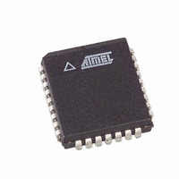
AT89LP828-20JU Atmel, AT89LP828-20JU Datasheet - Page 46

AT89LP828-20JU
Manufacturer Part Number
AT89LP828-20JU
Description
MCU 8051 8K FLASH SPI 32PLCC
Manufacturer
Atmel
Series
89LPr
Datasheet
1.AT89LP428-20AU.pdf
(149 pages)
Specifications of AT89LP828-20JU
Core Processor
8051
Core Size
8-Bit
Speed
20MHz
Connectivity
SPI, UART/USART
Peripherals
Brown-out Detect/Reset, POR, PWM, WDT
Number Of I /o
30
Program Memory Size
8KB (8K x 8)
Program Memory Type
FLASH
Eeprom Size
1K x 8
Ram Size
768 x 8
Voltage - Supply (vcc/vdd)
2.4 V ~ 5.5 V
Oscillator Type
Internal
Operating Temperature
-40°C ~ 85°C
Package / Case
32-PLCC
Processor Series
AT89x
Core
8051
Data Bus Width
8 bit
Data Ram Size
768 B
Interface Type
2-Wire, SPI
Maximum Clock Frequency
20 MHz
Number Of Programmable I/os
30
Number Of Timers
3
Maximum Operating Temperature
+ 85 C
Mounting Style
SMD/SMT
3rd Party Development Tools
PK51, CA51, A51, ULINK2
Development Tools By Supplier
AT89ISP
Minimum Operating Temperature
- 40 C
Lead Free Status / RoHS Status
Lead free / RoHS Compliant
Data Converters
-
Lead Free Status / Rohs Status
Details
Available stocks
Company
Part Number
Manufacturer
Quantity
Price
Table 11-3.
46
TMOD Address = 089H
Not Bit Addressable
Symbol
GATE1
C/T1
T1M1
T1M0
GATE0
C/T0
T0M1
T0M0
Bit
AT89LP428/828
GATE1
Function
Timer 1 Gating Control. When set. Timer/Counter 1 is enabled only while INT1 pin is high and TR1 control pin is set.
When cleared, Timer 1 is enabled whenever TR1 control bit is set.
Timer or Counter Selector 1. Cleared for Timer operation (input from internal system clock). Set for Counter operation
(input from T1 input pin). C/T1 must be zero when using Timer 1 in PWM mode.
Mode
Timer 0 Gating Control. When set. Timer/Counter 0 is enabled only while INT0 pin is high and TR0 control pin is set.
When cleared, Timer 0 is enabled whenever TR0 control bit is set.
Timer or Counter Selector 0. Cleared for Timer operation (input from internal system clock). Set for Counter operation
(input from T0 input pin). C/T0 must be zero when using Timer 0 in PWM mode.
Mode
7
TMOD – Timer/Counter Mode Control Register
0
1
2
3
0
1
2
3
T1M1
T0M1
0
0
1
1
0
0
1
1
C/T1
6
T1M0
T0M0
0
1
0
1
0
1
0
1
Timer 1 Operation
Variable 9 – 16-bit Timer mode. 8-bit Timer/Counter TH1 with TL1 as 1- to 8-bit prescaler.
16-bit Auto-reload mode. TH1 and TL1 are cascaded to form a 16-bit Timer/Counter that is
reloaded with RH1 and RL1 each time it overflows.
8-bit Auto-reload mode. 8-bit Timer/Counter TL1 is reloaded from TH1 each time it overflows.
Timer/Counter 1 is stopped
Timer 0 Operation
Variable 9 – 16-bit Timer Mode. 8-bit Timer/Counter TH0 with TL0 as 1- to 8-bit prescaler.
16-bit Auto-reload mode. TH0 and TL0 are cascaded to form a 16-bit Timer/Counter that is
reloaded with RH0 and RL0 each time it overflows.
8-bit Auto-reload mode. 8-bit Timer/Counter TL0 is reloaded from TH0 each time it overflows.
Split Timer Mode. TL0 is an 8-bit Timer/Counter controlled by the standard Timer 0 control
bits. TH0 is an 8-bit timer only controlled by Timer 1 control bits.
T1M1
5
T1M0
4
GATE0
3
C/T0
2
Reset Value = 0000 0000B
T0M0
1
T0M1
0
3654A–MICRO–8/09


