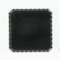
ATTINY861-20MU Atmel, ATTINY861-20MU Datasheet

ATTINY861-20MU
Specifications of ATTINY861-20MU
Available stocks
Related parts for ATTINY861-20MU
ATTINY861-20MU Summary of contents
Page 1
... Industrial Temperature Range • Low Power Consumption – Active Mode (1 MHz System Clock): 300 µA @ 1.8V – Power-Down Mode: 0.1 µA at 1.8V ® 8-Bit Microcontroller 8-bit Microcontroller with 2/4/8K Bytes In-System Programmable Flash ATtiny261/V ATtiny461/V ATtiny861/V Summary 2588ES–AVR–08/10 ...
Page 2
Pin Configurations Figure 1-1. Pinout ATtiny261/461/861 and ATtiny261V/461V/861V (MOSI/DI/SDA/OC1A/PCINT8) PB0 (MISO/DO/OC1A/PCINT9) PB1 (SCK/USCK/SCL/OC1B/PCINT10) PB2 (ADC7/OC1D/CLKI/XTAL1/PCINT12) PB4 (ADC8/OC1D/CLKO/XTAL2/PCINT13) PB5 (ADC9/INT0/T0/PCINT14) PB6 (ADC10/RESET/PCINT15) PB7 (OC1B/PCINT11) PB3 (ADC7/OC1D/CLKI/XTAL1/PCINT12) PB4 (ADC8/OC1D/CLKO/XTAL2/PCINT13) PB5 Note: To ensure mechanical stability the center pad underneath the QFN/MLF ...
Page 3
Pin Descriptions 1.1.1 VCC Supply voltage. 1.1.2 GND Ground. 1.1.3 AVCC Analog supply voltage. This is the supply voltage pin for the Analog-to-digital Converter (ADC), the analog comparator, the Brown-Out Detector (BOD), the internal voltage reference and Port A. ...
Page 4
Overview ATtiny261/461/861 are low-power CMOS 8-bit microcontrollers based on the AVR enhanced RISC architecture. By executing powerful instructions in a single clock cycle, the ATtiny261/461/861 achieves throughputs approaching 1 MIPS per MHz allowing the system designer to optimize power ...
Page 5
... The device is manufactured using Atmel’s high density non-volatile memory technology. The On-chip ISP Flash allows the Program memory to be re-programmed In-System through an SPI serial interface conventional non-volatile memory programmer On-chip boot code running on the AVR core ...
Page 6
... About 3.1 Resources A comprehensive set of drivers, application notes, data sheets and descriptions on development tools are available for download at http://www.atmel.com/avr. 3.2 Code Examples This documentation contains simple code examples that briefly show how to use various parts of the device. These code examples assume that the part specific header file is included before compilation ...
Page 7
Register Summary Address Name Bit 7 0x3F (0x5F) SREG I 0x3E (0x5E) SPH – 0x3D (0x5D) SPL SP7 0x3C (0x5C) Reserved 0x3B (0x5B) GIMSK INT1 0x3A (0x5A) GIFR INTF1 0x39 (0x59) TIMSK OCIE1D 0x38 (0x58) TIFR OCF1D 0x37 (0x57) ...
Page 8
Note: 1. For compatibility with future devices, reserved bits should be written to zero if accessed. Reserved I/O memory addresses should never be written. 2. I/O Registers within the address range 0x00 - 0x1F are directly bit-accessible using the SBI ...
Page 9
Instruction Set Summary Mnemonics Operands ARITHMETIC AND LOGIC INSTRUCTIONS ADD Rd, Rr Add two Registers ADC Rd, Rr Add with Carry two Registers ADIW Rdl,K Add Immediate to Word SUB Rd, Rr Subtract two Registers SUBI Rd, K Subtract ...
Page 10
Mnemonics Operands ASR Rd Arithmetic Shift Right SWAP Rd Swap Nibbles BSET s Flag Set BCLR s Flag Clear BST Rr, b Bit Store from Register to T BLD Rd, b Bit load from T to Register SEC Set Carry ...
Page 11
... Notes: 1. These devices can also be supplied in wafer form. Please contact your local Atmel sales office for detailed ordering informa- tion and minimum quantities. 2. All packages are Pb-free, halide-free and fully green and they comply with the European directive for Restriction of Hazard- ous Substances (RoHS) ...
Page 12
... Notes: 1. These devices can also be supplied in wafer form. Please contact your local Atmel sales office for detailed ordering informa- tion and minimum quantities. 2. All packages are Pb-free, halide-free and fully green and they comply with the European directive for Restriction of Hazard- ous Substances (RoHS) ...
Page 13
... Wide, Plastic Dual Inline Package (PDIP) 20S2 20-lead, 0.300" Wide, Plastic Gull Wing Smal Outline Package (SOIC) 2588ES–AVR–08/10 (4) Ordering Code ATtiny861V-10MU ATtiny861V-10MUR ATtiny861V-10PU ATtiny861V-10SU ATtiny861V-10SUR ATtiny861-20MU ATtiny861-20MUR ATtiny861-20PU ATtiny861-20SU ATtiny861-20SUR 188. Package Type (2) Package Operational Range 32M1-A 32M1-A Industrial 20P3 (-40° ...
Page 14
Packaging Information 7.1 32M1 Pin TOP VIEW Pin #1 Notch (0. BOTTOM VIEW Note: JEDEC Standard MO-220, Fig. 2 (Anvil Singulation), VHHD-2. 2325 Orchard Parkway San ...
Page 15
A SEATING PLANE Notes: 1. This package conforms to JEDEC reference MS-001, Variation AD. 2. Dimensions D and E1 do not include mold Flash or Protrusion. Mold Flash or Protrusion shall not exceed 0.25 mm ...
Page 16
ATtiny261/461/861 16 2588ES–AVR–08/10 ...
Page 17
... The revision letter in this section refers to the revision of the ATtiny461 device. 8.2.1 Rev B Yield improvement. No known errata. 8.2.2 Rev A No known errata. 8.3 Errata ATtiny861 The revision letter in this section refers to the revision of the ATtiny861 device. 8.3.1 Rev B No known errata. 8.3.2 Rev A Not sampled. 2588ES–AVR–08/10 17 ...
Page 18
Datasheet Revision History Please note that the referring page numbers in this section refer to the complete document. 9.1 Rev. 2588E – 08/10 Added tape and reel in Buffer” on page 9.2 Rev. 2588D – 06/10 1. Removed “Preliminary” ...
Page 19
Updated Figures: – – 7. Added Table: – 8. Updated Tables: – – – – 9. Updated Register Descriptions: – – – 10. Updated assembly program example in section 11. Updated wise noted).” on page 9.4 Rev. 2588B ...
Page 20
... Disclaimer: The information in this document is provided in connection with Atmel products. No license, express or implied, by estoppel or otherwise, to any intellectual property right is granted by this document or in connection with the sale of Atmel products. EXCEPT AS SET FORTH IN ATMEL’S TERMS AND CONDI- TIONS OF SALE LOCATED ON ATMEL’S WEB SITE, ATMEL ASSUMES NO LIABILITY WHATSOEVER AND DISCLAIMS ANY EXPRESS, IMPLIED OR STATUTORY WARRANTY RELATING TO ITS PRODUCTS INCLUDING, BUT NOT LIMITED TO, THE IMPLIED WARRANTY OF MERCHANTABILITY, FITNESS FOR A PARTICULAR PURPOSE, OR NON-INFRINGEMENT ...


