PIC16C56A/JW Microchip Technology, PIC16C56A/JW Datasheet - Page 42
PIC16C56A/JW
Manufacturer Part Number
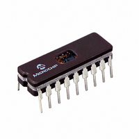
PIC16C56A/JW
Description
IC MCU EPROM 1KX12 18CDIP
Manufacturer
Microchip Technology
Series
PIC® 16Cr
Specifications of PIC16C56A/JW
Core Processor
PIC
Core Size
8-Bit
Speed
20MHz
Peripherals
POR, WDT
Number Of I /o
12
Program Memory Size
1.5KB (1K x 12)
Program Memory Type
EPROM, UV
Ram Size
25 x 8
Voltage - Supply (vcc/vdd)
3 V ~ 5.5 V
Oscillator Type
External
Operating Temperature
0°C ~ 70°C
Package / Case
18-CDIP (0.300", 7.62mm) Window
Lead Free Status / RoHS Status
Contains lead / RoHS non-compliant
Eeprom Size
-
Data Converters
-
Connectivity
-
Available stocks
Company
Part Number
Manufacturer
Quantity
Price
Company:

Part Number:
PIC16C56A/JW
Manufacturer:
Microchip Technology
Quantity:
2


PIC16C5X
8.2
An 8-bit counter is available as a prescaler for the
Timer0 module, or as a postscaler for the Watchdog
Timer (WDT), respectively (Section 9.2.1). For simplic-
ity, this counter is being referred to as “prescaler”
throughout this data sheet. Note that the prescaler may
be used by either the Timer0 module or the WDT, but
not both. Thus, a prescaler assignment for the Timer0
module means that there is no prescaler for the WDT,
and vice-versa.
The PSA and PS<2:0> bits (OPTION<3:0>) determine
prescaler assignment and prescale ratio.
When assigned to the Timer0 module, all instructions
writing
MOVWF 1, BSF 1,x, etc.) will clear the prescaler.
When assigned to WDT, a CLRWDT instruction will clear
the prescaler along with the WDT. The prescaler is nei-
ther readable nor writable. On a RESET, the prescaler
contains all '0's.
8.2.1
The prescaler assignment is fully under software con-
trol (i.e., it can be changed “on the fly” during program
execution). To avoid an unintended device RESET, the
following instruction sequence (Example 8-1) must be
executed when changing the prescaler assignment
from Timer0 to the WDT.
DS30453D-page 40
to
Prescaler
SWITCHING PRESCALER
ASSIGNMENT
the
TMR0
register
(e.g.,
CLRF 1,
Preliminary
EXAMPLE 8-1:
To change prescaler from the WDT to the Timer0 mod-
ule, use the sequence shown in Example 8-2. This
sequence must be used even if the WDT is disabled. A
CLRWDT instruction should be executed before switch-
ing the prescaler.
EXAMPLE 8-2:
CLRWDT
MOVLW
OPTION
CLRWDT
CLRF
MOVLW
OPTION
CLRWDT
MOVLW
OPTION
B'xxxx0xxx'
TMR0
B'00xx1111’ ;Last 3 instructions in
B'00xx1xxx’ ;Set Prescaler to
(TIMER0 WDT)
(WDT TIMER0)
CHANGING PRESCALER
CHANGING PRESCALER
2002 Microchip Technology Inc.
;are required only if
;Clear WDT
;Clear TMR0 & Prescaler
;PS<2:0> are 000 or
;001
;Clear WDT and
;prescaler
;Select TMR0, new
;prescale value and
;clock source
;desired
;desired WDT rate
this example
Related parts for PIC16C56A/JW
Image
Part Number
Description
Manufacturer
Datasheet
Request
R

Part Number:
Description:
Manufacturer:
Microchip Technology Inc.
Datasheet:

Part Number:
Description:
IC MCU OTP 1KX12 18SOIC
Manufacturer:
Microchip Technology
Datasheet:

Part Number:
Description:
IC MCU OTP 1KX12 18DIP
Manufacturer:
Microchip Technology
Datasheet:
Part Number:
Description:
IC MCU OTP 1KX12 18DIP
Manufacturer:
Microchip Technology
Datasheet:
Part Number:
Description:
IC MCU OTP 1KX12 18DIP
Manufacturer:
Microchip Technology
Datasheet:
Part Number:
Description:
IC MCU OTP 1KX12 18DIP
Manufacturer:
Microchip Technology
Datasheet:
Part Number:
Description:
IC MCU OTP 1KX12 18SOIC
Manufacturer:
Microchip Technology
Datasheet:
Part Number:
Description:
IC MCU OTP 1KX12 18DIP
Manufacturer:
Microchip Technology
Datasheet:
Part Number:
Description:
IC MCU OTP 1KX12 18SOIC
Manufacturer:
Microchip Technology
Datasheet:

Part Number:
Description:
IC MCU OTP 1KX12 20SSOP
Manufacturer:
Microchip Technology
Datasheet:
Part Number:
Description:
IC MCU OTP 1KX12 20SSOP
Manufacturer:
Microchip Technology
Datasheet:
Part Number:
Description:
IC MCU OTP 1KX12 18SOIC
Manufacturer:
Microchip Technology
Datasheet:
Part Number:
Description:
IC MCU OTP 1KX12 18DIP
Manufacturer:
Microchip Technology
Datasheet:
Part Number:
Description:
IC MCU OTP 1KX12 18DIP
Manufacturer:
Microchip Technology
Datasheet:
Part Number:
Description:
IC MCU OTP 1KX12 18DIP
Manufacturer:
Microchip Technology
Datasheet: