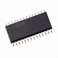
Z8F0422SJ020EG Zilog, Z8F0422SJ020EG Datasheet - Page 154

Z8F0422SJ020EG
Manufacturer Part Number
Z8F0422SJ020EG
Description
IC ENCORE MCU FLASH 4K 28SOIC
Manufacturer
Zilog
Series
Encore!® XP®r
Datasheet
1.Z8F08200100KIT.pdf
(264 pages)
Specifications of Z8F0422SJ020EG
Core Processor
Z8
Core Size
8-Bit
Speed
20MHz
Connectivity
I²C, IrDA, SPI, UART/USART
Peripherals
Brown-out Detect/Reset, POR, PWM, WDT
Number Of I /o
19
Program Memory Size
4KB (4K x 8)
Program Memory Type
FLASH
Ram Size
1K x 8
Voltage - Supply (vcc/vdd)
2.7 V ~ 3.6 V
Data Converters
A/D 5x10b
Oscillator Type
Internal
Operating Temperature
-40°C ~ 105°C
Package / Case
28-SOIC (7.5mm Width)
Processor Series
Z8F042xx
Core
eZ8
Data Bus Width
8 bit
Data Ram Size
1 KB
Interface Type
I2C, SPI, UART
Maximum Clock Frequency
20 MHz
Number Of Programmable I/os
19
Number Of Timers
2
Operating Supply Voltage
2.7 V to 3.6 V
Maximum Operating Temperature
+ 105 C
Mounting Style
SMD/SMT
Minimum Operating Temperature
- 40 C
On-chip Adc
10 bit, 5 Channel
Lead Free Status / RoHS Status
Lead free / RoHS Compliant
Eeprom Size
-
Lead Free Status / Rohs Status
Details
Other names
269-4142
Z8F0422SJ020EG
Z8F0422SJ020EG
- Current page: 154 of 264
- Download datasheet (6Mb)
Table 72. I
PS022517-0508
BITS
FIELD
RESET
R/W
ADDR
I
2
C Control Register
2
C Control Register (I2CCTL)
R/W
IEN
7
RD—Read
This bit indicates the direction of transfer of the data. It is active High during a read. The
status of this bit is determined by the least-significant bit of the I
START bit is set.
TAS—Transmit Address State
This bit is active High while the address is being shifted out of the I
DSS—Data Shift State
This bit is active High while data is being shifted to or from the I
NCKI—NACK Interrupt
This bit is set high when a Not Acknowledge condition is received or sent and neither the
START
cleared by setting the
perform a
The I
IEN—I
1 = The I
0 = The I
START—Send Start Condition
This bit sends the Start condition. Once asserted, it is cleared by the I
sends the START condition or if the IEN bit is deasserted. If this bit is 1, it cannot be
cleared to 0 by writing to the register. After this bit is set, the Start condition is sent if
there is data in the I
ters, the I
the I
and the acknowledge phase completes. If the STOP bit is also set, it also waits until the
STOP condition is sent before sending the START condition.
STOP—Send Stop Condition
This bit causes the I
register has completed transmission or after a byte is received in a receive operation. Once
2
2
C Controller is shifting out data, it generates a START condition after the byte shifts
C Control Register
nor the
2
START
C Enable
R/W1
2
2
2
C transmitter and receiver are enabled.
C transmitter and receiver are disabled.
STOP
C Controller waits until the data register is written. If this bit is set while
6
STOP
or a repeated
2
2
C Data or I
C Controller to issue a STOP condition after the byte in the I
bit is active. When set, this bit generates an interrupt that can only be
STOP
R/W1
START
5
(Table
or
START
2
STOP
72) enables the I
C Shift register. If there is no data in one of these regis-
BIRQ
R/W
4
.
bit, allowing you to specify whether you want to
F52H
0
R/W
TXI
3
2
C operation.
Z8 Encore! XP
R/W1
NAK
2
Product Specification
2
2
C Shift register after the
C Shift Register.
2
FLUSH
C Shift Register.
2
C Controller after it
W1
1
®
F0822 Series
I2C Controller
FILTEN
2
R/W
C Shift
0
141
Related parts for Z8F0422SJ020EG
Image
Part Number
Description
Manufacturer
Datasheet
Request
R

Part Number:
Description:
Communication Controllers, ZILOG INTELLIGENT PERIPHERAL CONTROLLER (ZIP)
Manufacturer:
Zilog, Inc.
Datasheet:

Part Number:
Description:
KIT DEV FOR Z8 ENCORE 16K TO 64K
Manufacturer:
Zilog
Datasheet:

Part Number:
Description:
KIT DEV Z8 ENCORE XP 28-PIN
Manufacturer:
Zilog
Datasheet:

Part Number:
Description:
DEV KIT FOR Z8 ENCORE 8K/4K
Manufacturer:
Zilog
Datasheet:

Part Number:
Description:
KIT DEV Z8 ENCORE XP 28-PIN
Manufacturer:
Zilog
Datasheet:

Part Number:
Description:
DEV KIT FOR Z8 ENCORE 4K TO 8K
Manufacturer:
Zilog
Datasheet:

Part Number:
Description:
CMOS Z8 microcontroller. ROM 16 Kbytes, RAM 256 bytes, speed 16 MHz, 32 lines I/O, 3.0V to 5.5V
Manufacturer:
Zilog, Inc.
Datasheet:

Part Number:
Description:
Low-cost microcontroller. 512 bytes ROM, 61 bytes RAM, 8 MHz
Manufacturer:
Zilog, Inc.
Datasheet:

Part Number:
Description:
Z8 4K OTP Microcontroller
Manufacturer:
Zilog, Inc.
Datasheet:

Part Number:
Description:
CMOS SUPER8 ROMLESS MCU
Manufacturer:
Zilog, Inc.
Datasheet:

Part Number:
Description:
SL1866 CMOSZ8 OTP Microcontroller
Manufacturer:
Zilog, Inc.
Datasheet:

Part Number:
Description:
SL1866 CMOSZ8 OTP Microcontroller
Manufacturer:
Zilog, Inc.
Datasheet:

Part Number:
Description:
OTP (KB) = 1, RAM = 125, Speed = 12, I/O = 14, 8-bit Timers = 2, Comm Interfaces Other Features = Por, LV Protect, Voltage = 4.5-5.5V
Manufacturer:
Zilog, Inc.
Datasheet:

Part Number:
Description:
Manufacturer:
Zilog, Inc.
Datasheet:


