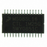
MC9S08SL16CTL Freescale Semiconductor, MC9S08SL16CTL Datasheet - Page 193

MC9S08SL16CTL
Manufacturer Part Number
MC9S08SL16CTL
Description
MCU 16KB FLASH SLIC 28TSSOP
Manufacturer
Freescale Semiconductor
Series
HCS08r
Datasheet
1.DEMO9S08EL32.pdf
(356 pages)
Specifications of MC9S08SL16CTL
Core Processor
HCS08
Core Size
8-Bit
Speed
40MHz
Connectivity
I²C, LIN, SCI, SPI
Peripherals
LVD, POR, PWM, WDT
Number Of I /o
22
Program Memory Size
16KB (16K x 8)
Program Memory Type
FLASH
Eeprom Size
256 x 8
Ram Size
512 x 8
Voltage - Supply (vcc/vdd)
2.7 V ~ 5.5 V
Data Converters
A/D 16x10b
Oscillator Type
External
Operating Temperature
-40°C ~ 85°C
Package / Case
28-TSSOP
Processor Series
S08SL
Core
HCS08
Data Bus Width
8 bit
Data Ram Size
512 B
Interface Type
I2C/SCI/SPI
Maximum Clock Frequency
40 MHz
Number Of Programmable I/os
22
Number Of Timers
6
Operating Supply Voltage
5.5 V
Maximum Operating Temperature
+ 85 C
Mounting Style
SMD/SMT
3rd Party Development Tools
EWS08
Development Tools By Supplier
DEMO9S08EL32, DEMO9S08EL32AUTO
Minimum Operating Temperature
- 40 C
On-chip Adc
16-ch x 10-bit
Package
28TSSOP
Family Name
HCS08
Maximum Speed
40 MHz
For Use With
DEMO9S08EL32 - BOARD DEMO FOR 9S08 EL MCUDEMO9S08EL32AUTO - DEMO BOARD EL32 AUTO
Lead Free Status / RoHS Status
Lead free / RoHS Compliant
Available stocks
Company
Part Number
Manufacturer
Quantity
Price
Company:
Part Number:
MC9S08SL16CTL
Manufacturer:
Freescale
Quantity:
2 359
- Current page: 193 of 356
- Download datasheet (9Mb)
12.3.3
In LIN operating mode (BTM = 0), the SLCBT is updated by the SLIC upon reception of a LIN break-sync
combination and provides the number of SLIC clock counts that equal one LIN bit time to the user
software. This value can be used by the software to calculate the clock drift in the oscillator as an offset to
a known count value (based on nominal oscillator frequency and LIN bus speed). The user software can
then trim the oscillator to compensate for clock drift. Refer to
SLIC,” for more information on this procedure. The user should only read the bit time value from
SLCBTH and SLCBTL in the interrupt service routine code for reception of the identifier byte. Reads at
any other time during LIN activity may not provide reliable results.
When in byte transfer mode (BTM = 1), the SLCBT must be written by the user to set the length of one
bit at the desired bit rate in SLIC clock counts. The user software must initialize this number prior to
sending or receiving data, based on the input clock selection, prescaler stage choice, and desired bit rate.
This setting is similar to choosing an input capture or output compare value for a timer. A write to both
registers is required to update the bit time value.
Freescale Semiconductor
RXFP[2:0]
000
001
010
011
100
101
110
111
SLIC Bit Time Registers (SLCBTH, SLCBTL)
Digital RX Filter
Clock Prescaler
In this subsection, the SLIC bit time registers are collectively referred to as
SLCBT.
The SLIC bit time will not be updated until a write of the SLCBTL has
occurred.
(Divide by)
1
2
3
4
5
6
7
8
MC9S08EL32 Series and MC9S08SL16 Series Data Sheet, Rev. 3
Table 12-3. Digital Receive Filter Clock Prescaler
16.00
24.00
32.00
40.00
48.00
56.00
64.00
8.00
2
12.00
16.00
20.00
24.00
28.00
32.00
4.00
8.00
4
10.67
13.33
16.00
18.67
21.33
2.67
5.33
8.00
6
NOTE
NOTE
Filter Input Clock (SLIC clock in MHz)
10.00
12.00
14.00
16.00
2.00
4.00
6.00
8.00
8
Max Filter Delay (in μs)
11.20
12.80
1.60
3.20
4.80
6.40
8.00
9.60
Section 12.6.17, “Oscillator Trimming with
10
10.67
1.33
2.67
4.00
5.33
6.67
8.00
9.33
12
1.14
2.29
3.43
4.57
5.71
6.86
8.00
9.14
14
1.00
2.00
3.00
4.00
5.00
6.00
7.00
8.00
16
0.89
1.78
2.67
3.56
4.44
5.33
6.22
7.11
18
0.80
1.60
2.40
3.20
4.00
4.80
5.60
6.40
20
195
Related parts for MC9S08SL16CTL
Image
Part Number
Description
Manufacturer
Datasheet
Request
R
Part Number:
Description:
Manufacturer:
Freescale Semiconductor, Inc
Datasheet:
Part Number:
Description:
Manufacturer:
Freescale Semiconductor, Inc
Datasheet:
Part Number:
Description:
Manufacturer:
Freescale Semiconductor, Inc
Datasheet:
Part Number:
Description:
Manufacturer:
Freescale Semiconductor, Inc
Datasheet:
Part Number:
Description:
Manufacturer:
Freescale Semiconductor, Inc
Datasheet:
Part Number:
Description:
Manufacturer:
Freescale Semiconductor, Inc
Datasheet:
Part Number:
Description:
Manufacturer:
Freescale Semiconductor, Inc
Datasheet:
Part Number:
Description:
Manufacturer:
Freescale Semiconductor, Inc
Datasheet:
Part Number:
Description:
Manufacturer:
Freescale Semiconductor, Inc
Datasheet:
Part Number:
Description:
Manufacturer:
Freescale Semiconductor, Inc
Datasheet:
Part Number:
Description:
Manufacturer:
Freescale Semiconductor, Inc
Datasheet:
Part Number:
Description:
Manufacturer:
Freescale Semiconductor, Inc
Datasheet:
Part Number:
Description:
Manufacturer:
Freescale Semiconductor, Inc
Datasheet:
Part Number:
Description:
Manufacturer:
Freescale Semiconductor, Inc
Datasheet:
Part Number:
Description:
Manufacturer:
Freescale Semiconductor, Inc
Datasheet:


