PIC16C745/JW Microchip Technology, PIC16C745/JW Datasheet - Page 65
PIC16C745/JW
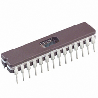
Manufacturer Part Number
PIC16C745/JW
Description
IC MCU EPROM8KX14 USB A/D 28CDIP
Manufacturer
Microchip Technology
Series
PIC® 16Cr
Datasheets
1.PIC16F616T-ISL.pdf
(8 pages)
2.PIC16C745-ISP.pdf
(165 pages)
3.PIC16C745-ISP.pdf
(6 pages)
4.PIC16C745-ISP.pdf
(6 pages)
Specifications of PIC16C745/JW
Core Processor
PIC
Core Size
8-Bit
Speed
24MHz
Connectivity
SCI, UART/USART, USB
Peripherals
Brown-out Detect/Reset, POR, PWM, WDT
Number Of I /o
22
Program Memory Size
14KB (8K x 14)
Program Memory Type
EPROM, UV
Ram Size
256 x 8
Voltage - Supply (vcc/vdd)
4.35 V ~ 5.25 V
Data Converters
A/D 5x8b
Oscillator Type
External
Operating Temperature
0°C ~ 70°C
Package / Case
28-CDIP (0.300", 7.62mm) Window
Lead Free Status / RoHS Status
Contains lead / RoHS non-compliant
Eeprom Size
-
Available stocks
Company
Part Number
Manufacturer
Quantity
Price
Company:

Part Number:
PIC16C745/JW
Manufacturer:
MICROCHIP
Quantity:
51
Part Number:
PIC16C745/JW
Manufacturer:
MICROCHIP/微芯
Quantity:
20 000


10.5.1.6
The control register provides various control and con-
figuration information for the USB.
REGISTER 10-6: USB CONTROL REGISTER (UCTRL: 195h)
2000 Microchip Technology Inc.
bit7
bit 7-6: Unimplemented: Read as ’0’
bit 5:
bit 4
bit 3:
bit 2:
bit 1:
bit 0:
U-0
—
tion. Clearing this bit allows the SIE to continue token processing. This bit is set by the SIE when a Setup
Token is received allowing software to dequeue any pending packet transactions in the BDT before resum-
ing token processing. The PKT_DIS bit is set under certain conditions such as back to back SETUP
tokens. This bit is not set on every SETUP token and can be modified only when UCTRL.SUSPND = 0.
perform remote wake-up. Software must set RESUME to 1 for 10 mS then clear it to 0 to enable remote
wake-up. For more information on RESUME signaling, see Section 7.1.7.5, 11.9 and 11.4.4 in the USB 1.1
specification.
generally be set in response to a UIDLE interrupt. It will generally be reset after an ACTIVITY interrupt.
V
driven, however the transceiver outputs are disabled.
USB Control Register (UCTRL)
SE0: Live Single Ended Zero
This status bit indicates that the D+ and D- lines are both pulled to low.
1 = Single ended zero being received
0 = Single ended zero not being received
PKT_DIS: The PKT_DIS bit informs the MCU that the SIE has disabled packet transmission and recep-
DEV_ATT: Device Attach
Enables the 3.3V output.
1 = When DEV_ATT is set, the V
0 = The V
RESUME: Setting this bit will allow the USB to execute resume signaling. This will allow the USB to
1 = Perform RESUME signaling
0 = Normal operation
SUSPND: Suspends USB operation and clocks and places the module in low power mode. This bit will
1 = USB module in power conserve mode
0 = USB module normal operation
Unimplemented: Read as ’0’
USB
U-0
—
regulation will be different between suspend and non-suspend modes. The V
USB
R-X
SE0
pins (D+ and D-) will be in a high impedance state
PKT_DIS DEV_ATT RESUME SUSPND
R/C-0
USB
R/W-0
pin will be driven with 3.3V (nominal)
Preliminary
R/W-0
R/W-0
PIC16C745/765
U-0
—
bit0
R = Readable bit
W = Writable bit
C = Clearable bit
U = Unimplemented bit,
-n = Value at POR reset
X = Don’t care
read as ‘0’
USB
DS41124C-page 65
pin will still be
Related parts for PIC16C745/JW
Image
Part Number
Description
Manufacturer
Datasheet
Request
R

Part Number:
Description:
MICRO CTRL 4K 4MHZ OTP 44PLCC
Manufacturer:
Microchip Technology
Datasheet:
Part Number:
Description:
MICRO CTRL 4K 20MHZ OTP 44PLCC
Manufacturer:
Microchip Technology
Datasheet:

Part Number:
Description:
MICRO CTRL 4K 20MHZ OTP 40DIP
Manufacturer:
Microchip Technology
Datasheet:
Part Number:
Description:
MICRO CTRL 4K 10MHZ OTP ET 40DIP
Manufacturer:
Microchip Technology
Datasheet:
Part Number:
Description:
MICRO CTRL 4K 10MHZ OTP 40DIP
Manufacturer:
Microchip Technology
Datasheet:
Part Number:
Description:
MICRO CTRL 4K 4MHZ OTP 40DIP
Manufacturer:
Microchip Technology
Datasheet:
Part Number:
Description:
MICRO CTRL 4K 4MHZ OTP 40DIP
Manufacturer:
Microchip Technology
Datasheet:

Part Number:
Description:
MICRO CTRL 4K 20MHZ EPROM 40CDIP
Manufacturer:
Microchip Technology
Datasheet:

Part Number:
Description:
8-Bit CMOS Microcontrollers with A/D Converter
Manufacturer:
Microchip Technology
Part Number:
Description:
8-Bit CMOS Microcontrollers with A/D Converter
Manufacturer:
Microchip Technology
Part Number:
Description:
8-Bit CMOS Microcontrollers with A/D Converter
Manufacturer:
Microchip Technology
Part Number:
Description:
8-Bit CMOS Microcontrollers with A/D Converter
Manufacturer:
Microchip Technology
Part Number:
Description:
8-Bit CMOS Microcontrollers with A/D Converter
Manufacturer:
Microchip Technology
Part Number:
Description:
8-Bit CMOS Microcontrollers with A/D Converter
Manufacturer:
Microchip Technology
Part Number:
Description:
8-Bit CMOS Microcontrollers with A/D Converter
Manufacturer:
Microchip Technology