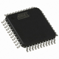
AT89C51RD2-RLRIM Atmel, AT89C51RD2-RLRIM Datasheet - Page 59

AT89C51RD2-RLRIM
Manufacturer Part Number
AT89C51RD2-RLRIM
Description
IC MCU FLASH 8051 EEP 64K 44VQFP
Manufacturer
Atmel
Series
89Cr
Datasheet
1.ATWEBDVK-02RC.pdf
(137 pages)
Specifications of AT89C51RD2-RLRIM
Core Processor
8051
Core Size
8-Bit
Speed
60MHz
Connectivity
SPI, UART/USART
Peripherals
POR, PWM, WDT
Number Of I /o
34
Program Memory Size
64KB (64K x 8)
Program Memory Type
FLASH
Ram Size
2K x 8
Voltage - Supply (vcc/vdd)
2.7 V ~ 5.5 V
Oscillator Type
External
Operating Temperature
-40°C ~ 85°C
Package / Case
44-TQFP, 44-VQFP
For Use With
AT89STK-11 - KIT STARTER FOR AT89C51RX2
Lead Free Status / RoHS Status
Contains lead / RoHS non-compliant
Eeprom Size
-
Data Converters
-
Other names
AT89C51RD2RLRIMTR
Available stocks
Company
Part Number
Manufacturer
Quantity
Price
- Current page: 59 of 137
- Download datasheet (2Mb)
15. Keyboard Interface
15.0.1
15.0.2
4235K–8051–05/08
Interrupt
Power Reduction Mode
The AT89C51RD2/ED2 implements a keyboard interface allowing the connection of a
8 x n matrix keyboard. It is based on 8 inputs with programmable interrupt capability on both
high or low level. These inputs are available as alternate function of P1 and allow to exit from
idle and power-down modes.
The keyboard interfaces with the C51 core through 3 special function registers: KBLS, the Key-
board Level Selection register (Table 15-3), KBE, the Keyboard interrupt Enable register
(Table 15-2), and KBF, the Keyboard Flag register (Table 15-1).
The keyboard inputs are considered as 8 independent interrupt sources sharing the same inter-
rupt vector. An interrupt enable bit (KBD in IE1) allows global enable or disable of the keyboard
interrupt (see Figure 15-1). As detailed in Figure 15-2 each keyboard input has the capability to
detect a programmable level according to KBLS. x bit value. Level detection is then reported in
interrupt flags KBF.x that can be masked by software using KBE. x bits.
This structure allow keyboard arrangement from 1 by n to 8 by n matrix and allows usage of P1
inputs for other purpose.
Figure 15-1. Keyboard Interface Block Diagram
Figure 15-2. Keyboard Input Circuitry
P1 inputs allow exit from idle and power-down modes as detailed in Section “Power Manage-
ment”, page 80.
P1:x
P1.0
P1.1
P1.2
P1.3
P1.4
P1.5
P1.6
P1.7
Vcc
Internal Pullup
Input Circuitry
Input Circuitry
Input Circuitry
Input Circuitry
Input Circuitry
Input Circuitry
Input Circuitry
Input Circuitry
KBLS.x
0
1
KBF.x
KBE.x
AT89C51RD2/ED2
KBD
IE1
Keyboard Interface
Interrupt Request
KBDIT
59
Related parts for AT89C51RD2-RLRIM
Image
Part Number
Description
Manufacturer
Datasheet
Request
R

Part Number:
Description:
AT89C51RD2-IM8-bit Flash Microcontroller
Manufacturer:
ATMEL Corporation
Datasheet:

Part Number:
Description:
Manufacturer:
Atmel Corporation
Datasheet:

Part Number:
Description:
IC 8051 MCU FLASH 64K 44VQFP
Manufacturer:
Atmel
Datasheet:

Part Number:
Description:
IC 8051 MCU FLASH 64K 44PLCC
Manufacturer:
Atmel
Datasheet:

Part Number:
Description:
IC 8051 MCU FLASH 64K 44PLCC
Manufacturer:
Atmel
Datasheet:

Part Number:
Description:
IC MCU FLASH 8051 EEP 64K 44PLCC
Manufacturer:
Atmel
Datasheet:

Part Number:
Description:
IC MCU FLASH 8051 EEP 64K 44VQFP
Manufacturer:
Atmel
Datasheet:

Part Number:
Description:
IC 8051 MCU FLASH 64K 44VQFP
Manufacturer:
Atmel
Datasheet:

Part Number:
Description:
IC MCU FLASH 8051 EEP 64K 44PLCC
Manufacturer:
Atmel
Datasheet:

Part Number:
Description:
MCU 8-Bit AT89 80C51 CISC 64KB Flash 3.3V/5V 64-Pin VQFP Tray
Manufacturer:
Atmel
Datasheet:

Part Number:
Description:
8-bit Flash Microcontroller
Manufacturer:
ATMEL Corporation
Datasheet:

Part Number:
Description:
8-bit Microcontrollers - MCU Microcontroller
Manufacturer:
Atmel
Datasheet:

Part Number:
Description:
IC MICRO CTRL 24MHZ 44TQFP
Manufacturer:
Atmel
Datasheet:

Part Number:
Description:
IC MICRO CTRL 24MHZ 44PLCC
Manufacturer:
Atmel
Datasheet:


