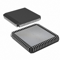
DS87C550-QNL Maxim Integrated Products, DS87C550-QNL Datasheet - Page 28

DS87C550-QNL
Manufacturer Part Number
DS87C550-QNL
Description
IC MCU EPROM ADC/PWM HS 68-PLCC
Manufacturer
Maxim Integrated Products
Series
87Cr
Datasheet
1.DS87C550-QNL.pdf
(49 pages)
Specifications of DS87C550-QNL
Core Processor
8051
Core Size
8-Bit
Speed
33MHz
Connectivity
EBI/EMI, SIO, UART/USART
Peripherals
Power-Fail Reset, PWM, WDT
Number Of I /o
55
Program Memory Size
8KB (8K x 8)
Program Memory Type
OTP
Ram Size
1K x 8
Voltage - Supply (vcc/vdd)
4.5 V ~ 5.5 V
Data Converters
A/D 6x10b
Oscillator Type
External
Operating Temperature
-40°C ~ 85°C
Package / Case
68-LCC, 68-PLCC
Lead Free Status / RoHS Status
Contains lead / RoHS non-compliant
Eeprom Size
-
Available stocks
Company
Part Number
Manufacturer
Quantity
Price
Company:
Part Number:
DS87C550-QNL
Manufacturer:
Maxim Integrated
Quantity:
10 000
Part Number:
DS87C550-QNL
Manufacturer:
DALLAS
Quantity:
20 000
WATCHDOG TIMER
The free-running watchdog timer, if enabled, will set a flag and cause a reset if not restarted by software
within the user selectable timeout period.
A typical application is to allow the flag to cause a reset. When the watchdog times out, it sets the
Watchdog Timer Reset Flag (WTRF=WDCON.2), which generates a reset if enabled by the Enable
Watchdog Timer Reset (EWT=WDCON.1) bit. In this way if the code execution goes awry and software
does not reset the watchdog as scheduled, the processor is put in a known good state: reset.
In a typical initialization, software selects the desired timeout period using the WD1:0 and the system
clock control bits. Then, it resets the timer and enables the processor reset function. After enabling the
processor reset function, software must then reset the timer before its timeout period or hardware will
reset the CPU. A Timed Access circuit protects both the EWT and the Watchdog Reset control (RWT =
WDCON.0) bits. This prevents errant software from accidentally clearing the watchdog.
The watchdog timer is controlled by the Clock Control (CKCON) and the Watchdog Control (WDCON)
SFRs. CKCON.7 and CKCON.6 are WD1 and WD0 respectively, and they select the watchdog timeout
period. Of course, the 4X/
timeout period. Selection of timeout is shown in Table 8.
WATCHDOG TIMEOUT VALUES Table 8
4X/
1
0
x
x
x
SETR.7
SETR.6
SETR.5
SETR.4
SETR.3
SETR.2
SETR.1
SETR.0
RSTR.7
RSTR.6
RSTR.5
RSTR.4
RSTR.3
RSTR.2
RSTR.1
RSTR.0
2X
CD1:0
00
00
01
10
11
TGFF1
TGFF0
CMS5
CMS4
CMS3
CMS2
CMS1
CMS0
CMTE1
CMTE0
CMR5
CMR4
CMR3
CMR2
CMR1
CMR0
WD1:0=00
2
2
2
2
2
15
16
17
17
25
INTERRUPT TIMEOUT (CLOCKS)
2X
SETR REGISTER FUNCTIONALITY
If 1 then P4.5 is set on a match between CMPH0:CMPL0 and Timer 2
If 1 then P4.4 is set on a match between CMPH0:CMPL0 and Timer 2
If 1 then P4.3 is set on a match between CMPH0:CMPL0 and Timer 2
If 1 then P4.2 is set on a match between CMPH0:CMPL0 and Timer 2
If 1 then P4.1 is set on a match between CMPH0:CMPL0 and Timer 2
If 1 then P4.0 is set on a match between CMPH0:CMPL0 and Timer 2
If 1 then P4.7 toggles on a match between CMPH2:CMPL2 and Timer 2
If 1 then P4.6 toggles on a match between CMPH2:CMPL2 and Timer 2
If 1 then P4.5 is reset on a match between CMPH1:CMPL1 and Timer 2
If 1 then P4.4 is reset on a match between CMPH1:CMPL1 and Timer 2
If 1 then P4.3 is reset on a match between CMPH1:CMPL1 and Timer 2
If 1 then P4.2 is reset on a match between CMPH1:CMPL1 and Timer 2
If 1 then P4.1 is reset on a match between CMPH1:CMPL1 and Timer 2
If 1 then P4.0 is reset on a match between CMPH1:CMPL1 and Timer 2
This bit toggles if CMPH2:CMPL2 and Timer 2 match and CMTE1 is 1
This bit toggles if CMPH2:CMPL2 and Timer 2 match and CMTE0 is 1
(PMR.3) and CD1:0 (PMR.7:6) system clock control bits also affect the
RSTR REGISTER FUNCTIONALITY
WD1:0=01
2
2
2
2
2
18
19
20
20
28
WD1:0=10
2
2
2
2
2
28 of 49
21
22
23
23
31
WD1:0=11
2
2
2
2
2
24
25
26
26
34
WD1:0=00
2
2
2
2
2
15
16
17
17
25
+512
+512
+512
+512
+512
RESET TIME-CLOCKS
WD1:0=01
2
2
2
2
2
18
19
20
20
28
+512
+512
+512
+512
+512
WD1:0=10
2
2
2
2
2
21
22
23
23
31
+512
+512
+512
+512
+512
WD1:0=11
2
2
2
2
2
24
25
26
26
34
+512
+512
+512
+512
+512


