PA75CD Cirrus Logic Inc, PA75CD Datasheet - Page 4
PA75CD
Manufacturer Part Number
PA75CD
Description
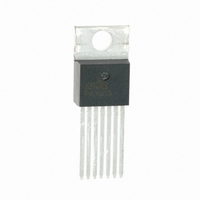
OP AMP DL PWR 40V 1.5A 7P TO220
Manufacturer
Cirrus Logic Inc
Series
Apex Precision Power™r
Datasheet
1.PA75CD.pdf
(5 pages)
Specifications of PA75CD
Amplifier Type
Power
Number Of Circuits
2
Slew Rate
1.4 V/µs
Gain Bandwidth Product
1.4MHz
Current - Input Bias
100nA
Voltage - Input Offset
1000µV
Current - Supply
8mA
Current - Output / Channel
1.5A
Voltage - Supply, Single/dual (±)
5 V ~ 40 V, ±2.5 V ~ 20 V
Operating Temperature
-25°C ~ 85°C
Mounting Type
Through Hole
Package / Case
TO-220-7
Number Of Channels
2
Voltage Gain Db
100 dB
Common Mode Rejection Ratio (min)
60 dB
Input Offset Voltage
15 mV
Operating Supply Voltage
30 V
Maximum Operating Temperature
+ 85 C
Mounting Style
Through Hole
Maximum Dual Supply Voltage
+/- 20 V
Minimum Operating Temperature
- 25 C
Lead Free Status / RoHS Status
Lead free / RoHS Compliant
Output Type
-
-3db Bandwidth
-
Lead Free Status / Rohs Status
Details
Other names
598-1347
Available stocks
Company
Part Number
Manufacturer
Quantity
Price

Company:
Part Number:
PA75CD
Manufacturer:
VISHAY
Quantity:
5 510
Part Number:
PA75CD
Manufacturer:
APEX
Quantity:
20 000


PA75
GENERAL
ations” which covers stability, supplies, heatsinking, mounting,
SOA interpretation, and specification interpretation. Visit www.
Cirrus.com for design tools that help automate tasks such as
calculations for stability, internal power dissipation, heatsink
selection; Apex Precision Power’s complete Application Notes
library; Technical Seminar Workbook; and Evaluation Kits.
STABILITY CONSIDERATIONS
op amps use output
stage topologies that
present special stabil-
ity problems. This is
primarily due to non-
complementary (both
d ev i c e s a re N P N )
output stages with a
mismatch in gain and
phase response for
different polarities of
output current. It is dif-
ficult for the op amp manufacturer to optimize compensation
for all operating conditions. For applications with load current
exceeding 300ma, oscillation may appear. The oscillation may
occur only with the output voltage swing at the negative or
positive half cycle. Under most operating and load conditions
acceptable stability can be achieved by providing a series RC
snubber network connected from the output to ground. The
recommended component values of the network are,R
10Ω and C
further details.
SAFE OPERATING AREA (SOA)
op amp. For a given application, the direction and magnitude
of the output current should be calculated or measured and
checked against the SOA curves. This is simple for resistive
loads but more complex for reactive and EMF generating loads.
4
Please read Application Note 1 “General Operating Consider-
All monolithic power
The SOA curves combine the effect of all limits for this power
10.0
1.0
0.1
1.0
SUPPLY TO OUTPUT DIFFERENTIAL VOLTAGE, V
TWO AMPLIFIERS
LOADED
ONE AMPLIFIER
LOADED
SN
= 0.01µF. Please refer to Application Note 1 for
DC, T
C
= 85°C
10.0
SOA
+
–
DC, T
C
= 25°C
R
10Ω
C
0.01µF
S
SN
SN
- V
O
100.0
SN
(V)
=
P r o d u c t I n n o v a t i o n F r o m
THERMAL CONSIDERATIONS
tab to which the monolithic is directly attached. The PA75CD
and CX may require a thermal washer, which is electrically
insulating since the tab is directly tied to -VS. This can result
in a thermal impedance RCS of up to 1˚C/W or greater.
to which the monolithic is directly attached. The solder connec-
tion of the heatslug to a minimum of 1 square inch foil area of
the printed circuit board will result in thermal performance of
25°C/W junction to air rating of the PA75CC. Solder connection
to an area of 1 to 2 square inches of foil is required for minimal
power applications
it is necessary to use surface mount techniques of heatsink-
ing. Surface mount techniques include the use of a surface
mount fan in combination with a surface mount heatsink on
the backside of the FR4/ PC board with through hole thermal
vias. Other highly thermal conductive substrate board materials
are available for maximum heat sinking.
MOUNTING PRECAUTIONS
1. Always use a heat sink. Even unloaded the PA75 can dis-
2. Avoid bending the leads. Such action can lead to internal
3. Always fasten the tab of the CD and CX package to the
4. Strain relief must be provided if there is any probability of
The PA75CD and CX have a large exposed copper heat
The PA75CC has a large exposed integrated copper heatslug
Where the PA75CC is used in higher power applications,
sipate up to .4 watts.
damage.
heat sink before the leads are soldered to fixed terminals.
axial stress to the leads.
35
30
25
20
15
10
5
0
0
TWO AMPLIFIERS
LOADED
ONE AMPLIFIER
LOADED
25
CASE TEMPERATURE, T
POWER DERATING
50
75
C
(°C)
100
PA75U
125
Related parts for PA75CD
Image
Part Number
Description
Manufacturer
Datasheet
Request
R

Part Number:
Description:
Development Kit
Manufacturer:
Cirrus Logic Inc
Datasheet:
Part Number:
Description:
Development Kit
Manufacturer:
Cirrus Logic Inc
Datasheet:


Part Number:
Description:
High-efficiency PFC + Fluorescent Lamp Driver Reference Design
Manufacturer:
Cirrus Logic Inc
Datasheet:
Part Number:
Description:
Development Kit
Manufacturer:
Cirrus Logic Inc
Datasheet:
Part Number:
Description:
Development Kit
Manufacturer:
Cirrus Logic Inc
Datasheet:

Part Number:
Description:
Development Kit
Manufacturer:
Cirrus Logic Inc
Datasheet:
Part Number:
Description:
Development Kit
Manufacturer:
Cirrus Logic Inc
Datasheet:
Part Number:
Description:
Development Kit
Manufacturer:
Cirrus Logic Inc
Datasheet:
Part Number:
Description:
Development Kit
Manufacturer:
Cirrus Logic Inc
Datasheet:

Part Number:
Description:
EVALUATION BOARD FOR CS8427
Manufacturer:
Cirrus Logic Inc
Datasheet:

Part Number:
Description:
BOARD EVAL FOR CS8416 RCVR
Manufacturer:
Cirrus Logic Inc
Datasheet:

Part Number:
Description:
EVALUATION BOARD FOR CS8420
Manufacturer:
Cirrus Logic Inc
Datasheet:

Part Number:
Description:
KIT DEVELOPMENT EP9315 ARM9
Manufacturer:
Cirrus Logic Inc
Datasheet:

Part Number:
Description:
KIT DEVELOPMENT EP9302 ARM9
Manufacturer:
Cirrus Logic Inc
Datasheet: