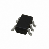
LMV841MG/NOPB National Semiconductor, LMV841MG/NOPB Datasheet - Page 15

LMV841MG/NOPB
Manufacturer Part Number
LMV841MG/NOPB
Description
IC OPAMP R-R I/O L-V L-P SC70-5
Manufacturer
National Semiconductor
Datasheet
1.LMV841MGNOPB.pdf
(22 pages)
Specifications of LMV841MG/NOPB
Amplifier Type
General Purpose
Number Of Circuits
1
Output Type
Rail-to-Rail
Slew Rate
2.5 V/µs
Gain Bandwidth Product
4.5MHz
Current - Input Bias
0.3pA
Voltage - Input Offset
50µV
Current - Supply
1.03mA
Current - Output / Channel
37mA
Voltage - Supply, Single/dual (±)
2.7 V ~ 12 V, ±1.35 V ~ 6 V
Operating Temperature
-40°C ~ 125°C
Mounting Type
Surface Mount
Package / Case
SC-70-5, SC-88A, SOT-323-5, SOT-353, 5-TSSOP
Lead Free Status / RoHS Status
Lead free / RoHS Compliant
-3db Bandwidth
-
Other names
LMV841MG
LMV841MGTR
LMV841MGTR
The resistor noise for the second example is:
The total noise at the input of the op amp is:
For the second example the input noise will, multiplied with
the noise gain, give an output noise of
In the first example the noise is dominated by the resistor
noise due to the very high resistor values, in the second ex-
ample the very low resistor values add only a negligible
contribution to the noise and now the dominating factor is the
op amp itself. When selecting the resistor values, it is impor-
tant to choose values that don't add extra noise to the appli-
cation. Choosing values above 100kΩ may increase the noise
too much. Low values will keep the noise within acceptable
levels; choosing very low values however, will not make the
noise even lower, but will increase the current of the circuit.
ACTIVE FILTER
The rail-to-rail input and output of the LMV841/LMV842/
LMV844 and the wide supply voltage range make these am-
plifiers ideal to use in numerous applications. One of the
typical applications is an active filter as shown in
This example is a band-pass filter, for which the pass band is
widened. This is achieved by cascading two band-pass filters,
with slightly different center frequencies.
The center frequency of the separate band-pass filters can be
calculated by:
In this example a filter was designed with its pass band at
10kHz. The two separate band-pass filters are designed to
have a center frequency of approximately 10% from the fre-
quency of the total filter:
FIGURE 4. Active Filter
Figure
20168358
4.
15
This will give for filter A:
and for filter B with C = 27nF:
Bandwidth can be calculated by:
For filter A this will give:
and for filter B:
The response of the two filters and the combined filter is
shown in
The responses of filter A and filter B are shown as the thin
lines in
as the thick line. Shifting the center frequencies of the sepa-
rate filters farther apart, will result in a wider band; however,
positioning the center frequencies too far apart will result in a
less flat gain within the band. For wider bands more band-
pass filters can be cascaded.
Tip: Use the WEBENCH internet tools at www.national.com
for your filter application.
Figure
Figure
FIGURE 5. Active Filter Curve
5; the response of the combined filter is shown
5.
R2 = 6.2KΩ
R1 = 2KΩ
R3 = 45Ω
C = 33nF
www.national.com
20168359


