PA107DP Cirrus Logic Inc, PA107DP Datasheet - Page 3
PA107DP
Manufacturer Part Number
PA107DP
Description
HI PWR AMP MODULE 3KV/US SLEW
Manufacturer
Cirrus Logic Inc
Series
Apex Precision Power™r
Specifications of PA107DP
Amplifier Type
Power
Number Of Circuits
1
Slew Rate
3000 V/µs
Gain Bandwidth Product
180MHz
Current - Input Bias
300pA
Voltage - Input Offset
5000µV
Current - Supply
30mA
Current - Output / Channel
1.5A
Voltage - Supply, Single/dual (±)
±20 V ~ 100 V
Operating Temperature
-25°C ~ 85°C
Mounting Type
Through Hole
Package / Case
12-SIP
Input Voltage Range (max)
400 V
Input Voltage Range (min)
20 V
Input Offset Voltage
5 mV
Output Current (typ)
1.5 A
Supply Current
1.5 A
Maximum Power Dissipation
62.5 W
Maximum Operating Temperature
+ 85 C
Mounting Style
Through Hole
Minimum Operating Temperature
- 20 C
Lead Free Status / RoHS Status
Contains lead / RoHS non-compliant
Output Type
-
-3db Bandwidth
-
Lead Free Status / Rohs Status
No
Other names
598-1793
Available stocks
Company
Part Number
Manufacturer
Quantity
Price

Part Number:
PA107DP
Manufacturer:
APEX
Quantity:
20 000


NOTES:
EXTERNAL CONNECTIONS
PA107DPU
POWER SUPPLY
VOLTAGE, +V
VOLTAGE, -V
VOLTAGE, +V
VOLTAGE, -V
CURRENT, QUIESCENT, +V
CURRENT, QUIESCENT, -V
CURRENT, QUIESCENT, -V
CURRENT, QUIESCENT, +V
THERMAL
RESISTANCE, AC, junction to case (Note 6)
RESISTANCE, DC junction to case
RESISTANCE, junction to air
TEMPERATURE RANGE, case
C1-2 = 10uF/A out (peak), electrolytic/tantalum, low frequency bypass.
C3-4 = 1uF 25V X7R ceramic capacitor recomended.
C5-6 = 1uF 200V X7R ceramic capacitor recomended.
IN
1
1uF
C3
+V
2
AUX
1. All Min/Max characteristics and specifications are guaranteed over the Specified Operating Condi-
2. Long term operation at the maximum junction temperature will result in reduced product life. Derate
3. Doubles for every 10ºC of case temperature increase.
4. +V
5. +V
6. Rating applies if the output current alternates between both output transistors at a rate faster than
1uF
C4
-V
tions. Typical performance characteristics and specifications are derived from measurements taken
at typical supply voltages and T
power dissipation to achieve high MTTF.
60Hz.
3
AUX
AUX
S
AUX
S
Parameter
AUX
S
GND
and −V
4
and –V
P r o d u c t T e c h n o l o g y F r o m
OPEN
5
S
denote the positive and negative supply voltages to the output stages.
AUX
AUX
S
AUX
OPEN
S
6
denote the positive and negative supply voltages to the input stages.
OPEN
7
1uF
C5
+V
8
S
1uF
C6
C
-V
9
= 25°C.
S
Test Conditions
-V
10
SP
+
C1
OUT
11
+V
12
SP
+
C2
-100
Min
-18
-25
20
10
20
20
Typ
-15
15
30
30
19
19
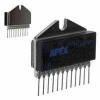
Formed leads available
See Package Style EE
Package Style DP
Max
100
-20
-10
1.5
18
35
35
21
21
30
85
2
PA107DP
12-pin SIP
Units
°C/W
°C/W
°C/W
mA
mA
mA
mA
°C
V
V
V
V
3
Related parts for PA107DP
Image
Part Number
Description
Manufacturer
Datasheet
Request
R

Part Number:
Description:
OP AMP 90V 5A TO-3-8 CE
Manufacturer:
Cirrus Logic Inc
Datasheet:

Part Number:
Description:
Development Kit
Manufacturer:
Cirrus Logic Inc
Datasheet:
Part Number:
Description:
Development Kit
Manufacturer:
Cirrus Logic Inc
Datasheet:


Part Number:
Description:
High-efficiency PFC + Fluorescent Lamp Driver Reference Design
Manufacturer:
Cirrus Logic Inc
Datasheet:
Part Number:
Description:
Development Kit
Manufacturer:
Cirrus Logic Inc
Datasheet:
Part Number:
Description:
Development Kit
Manufacturer:
Cirrus Logic Inc
Datasheet:

Part Number:
Description:
Development Kit
Manufacturer:
Cirrus Logic Inc
Datasheet:
Part Number:
Description:
Development Kit
Manufacturer:
Cirrus Logic Inc
Datasheet:
Part Number:
Description:
Development Kit
Manufacturer:
Cirrus Logic Inc
Datasheet:

Part Number:
Description:
EVALUATION BOARD FOR CS8427
Manufacturer:
Cirrus Logic Inc
Datasheet:

Part Number:
Description:
BOARD EVAL FOR CS8416 RCVR
Manufacturer:
Cirrus Logic Inc
Datasheet:

Part Number:
Description:
EVALUATION BOARD FOR CS8420
Manufacturer:
Cirrus Logic Inc
Datasheet:

Part Number:
Description:
KIT DEVELOPMENT EP9315 ARM9
Manufacturer:
Cirrus Logic Inc
Datasheet:

Part Number:
Description:
KIT DEVELOPMENT EP9302 ARM9
Manufacturer:
Cirrus Logic Inc
Datasheet: