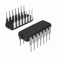
HA1-2540-5 Intersil, HA1-2540-5 Datasheet - Page 3

HA1-2540-5
Manufacturer Part Number
HA1-2540-5
Description
IC OP AMP 400MHZ MONO 14-CDIP
Manufacturer
Intersil
Datasheet
1.HA1-2540-5.pdf
(8 pages)
Specifications of HA1-2540-5
Amplifier Type
General Purpose
Number Of Circuits
1
Slew Rate
400 V/µs
Gain Bandwidth Product
400MHz
Current - Input Bias
5µA
Voltage - Input Offset
8000µV
Current - Supply
20mA
Current - Output / Channel
20mA
Voltage - Supply, Single/dual (±)
±5 V ~ 15 V
Operating Temperature
0°C ~ 75°C
Mounting Type
Through Hole
Package / Case
14-CDIP (0.300", 7.62mm)
Lead Free Status / RoHS Status
Contains lead / RoHS non-compliant
Output Type
-
-3db Bandwidth
-
Available stocks
Company
Part Number
Manufacturer
Quantity
Price
Part Number:
HA1-2540-5
Manufacturer:
HAR
Quantity:
20 000
Electrical Specifications
NOTES:
Test Circuits and Waveforms
10. Guaranteed range for output voltage is ±10V. Functional operation outside of this range is not guaranteed.
POWER REQUIREMENTS
Supply Current
Power Supply Rejection Ratio (Note 9)
3. R
4. V
5. V
6. A
7. Full power bandwidth guaranteed based on slew rate measurement using:
8. Refer to Test Circuits section of the data sheet.
9. V
SETTLE
INPUT
POINT
CM
O
V
SUPPLY
L
500Ω
A
B
= 1kΩ, V
= 10.
= 90mV.
= ±10V.
Vertical Scale: A = 0.5V/Div., B = 5.0V/Div.
= +5V, -15V and +15V, -5V.
200Ω
O
= ±10V.
LARGE SIGNAL RESPONSE
Horizontal Scale: 50ns/Div.
V+
+
-
V-
3
V
FIGURE 1. LARGE AND SMALL SIGNAL RESPONSE TEST CIRCUIT
SUPPLY
PARAMETER
0.001µF
0.001µF
V
2kΩ
5kΩ
1µF
1µF
IN
= ±15V, R
FIGURE 2. SETTLING TIME TEST CIRCUIT
L
= 1kΩ, C
+
-
PROBE
MONITOR
OUTPUT
HA-2540
L
< 10pF, Unless Otherwise Specified (Continued)
100
900
NOTES:
13. A
14. Load Capacitance should be less than 10pF. Turn on time delay
15. It is recommended that resistors be carbon composition and the
16. SETTLE POINT (Summing Node) capacitance should be less
typically 4ns.
feedback and summing network ratios be matched to 0.1%.
than 10pF. For optimum settling time results, it is recommended
that the test circuit be constructed directly onto the device pins. A
Tektronix 568 Sampling Oscilloscope with S-3A sampling heads
is recommended as a settle point monitor.
FPBW
V
V
OUT
= -10.
Vertical Scale: Input = 10mV/Div.; Output = 50mV/Div.
NOTES:
11. A
12. C
=
---------------------------
2πV PEAK
Slew Rate
V
L
TEMP (
= +10.
≤ 10pF.
Full
Full
SMALL SIGNAL RESPONSE
Horizontal Scale: 20ns/Div.
o
.
C)
MIN
60
-
TYP
20
70
MAX
25
-
UNITS
mA
dB


