MIC35152WD TR Micrel Inc, MIC35152WD TR Datasheet - Page 3
MIC35152WD TR
Manufacturer Part Number
MIC35152WD TR
Description
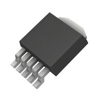
IC REG LDO 1.5A ADJ TO-252-5
Manufacturer
Micrel Inc
Datasheet
1.MIC35152WD_TR.pdf
(8 pages)
Specifications of MIC35152WD TR
Regulator Topology
Positive Adjustable
Voltage - Output
1.24 ~ 5.4 V
Voltage - Input
2.25 ~ 6 V
Voltage - Dropout (typical)
0.365V @ 1.5A
Number Of Regulators
1
Current - Output
1.5A (Min)
Operating Temperature
-40°C ~ 125°C
Mounting Type
Surface Mount
Package / Case
DPak, TO-252 (5 leads + tab)
Lead Free Status / RoHS Status
Lead free / RoHS Compliant
Current - Limit (min)
-
Other names
576-3613-2


Absolute Maximum Ratings
Supply Voltage (V
Enable Input Voltage (V
Power Dissipation .....................................Internally Limited
Junction Temperature .........................–40°C ≤ T
Storage Temperature (T
Lead Temperature (soldering, 5sec.)......................... 260°C
ESD Rating................................................................ Note 3
Electrical Characteristics
T
Notes:
1.
2.
3.
4.
5.
6.
7.
8.
Micrel, Inc.
Parameter
Output Voltage Line Regulation
Output Voltage Load Regulation
Dropout Voltage, V
Note 6
Ground Pin Current, Note 7
Ground Pin Current in Shutdown
Current Limit
Start-up Time
Enable Input
Enable Input Threshold
Enable Pin Input Current
Adjust Pin
Reference Voltage
Reference Voltage Temp.
Coefficient
Adjust Pin Bias Current
Adjust Pin Bias Current Temp.
Coefficient
October 2009
J
= 25°C with V
Exceeding the absolute maximum rating may damage the device.
The device is not guaranteed to function outside its operating rating.
Devices are ESD sensitive. Handling precautions recommended.
P
Specification for packaged product only.
V
specification does not apply due to a minimum input operating voltage of 2.25V.
I
Thermal regulation is defined as the change in output voltage at a time t after a change in power dissipation is applied, excluding load or line
regulation effects. Specifications are for a 200mA load pulse at V
GND
D(MAX)
DO
= V
is the quiescent current. I
= (T
IN
– V
J(MAX)
OUT
IN
– T
when V
IN
IN
= V
) ..................................... –0.3V to +6.5V
A
– V
) / θ
EN
OUT
OUT
JA
EN
s
= V
) ...................–65°C ≤ T
, where θ
)........................... –0.3V to +6.5V
decreased to 98% of its nominal output voltage with V
IN
OUT
= I
GND
+ 1V; I
JA
, depends upon the printed circuit layout. See “Applications Information.”
+ I
Condition
V
I
I
I
I
V
V
V
Regulator enable
Regulator shutdown
V
V
Note 8
(5)
OUT
OUT
OUT
OUT
IN
IL
OUT
EN
IL
IH
OUT
≤ 0.5V, V
≤ 0.8V (regulator shutdown)
= V
≥ 2.25V (regulator enabled)
OUT
(1)
= V
= 10mA to 1.5A
= 750mA
= 1.5A
= 1.5A
.
= 0
OUT
IN
= 10mA; bold values indicate –40°C < T
, I
+1.0V to 6.0V
OUT
IN
= V
= 10mA, C
J
J
≤ +125°C
≤ +150°C
OUT
+ 1V
IN
= 6V for t = 10ms.
OUT
3
= 47µF
Operating Ratings
Supply voltage (V
Enable Input Voltage (V
Junction Temperature Range .............–40°C ≤ T
Maximum Power Dissipation..................................... Note 4
Package Thermal Resistance
TO-252 (θ
TO-252 (θ
IN
= V
OUT
+1V. For output voltages below 1.75V, dropout voltage
JC
JA
) ........................................................3°C/W
) ......................................................56°C/W
IN
) ................................... +2.25V to +6.0V
J
< +125°C, unless otherwise noted.
EN
(2)
)................................ 0V to +6.0V
1.228
1.215
2.25
Min
1
1.240
0.06
Typ
225
365
0.2
1.0
2.7
0.1
11
45
15
20
40
M9999-102309-A
1.252
1.265
Max
350
600
150
120
0.5
4.0
0.8
30
30
75
80
1
2
4
MIC35152
J
≤ +125°C
ppm/°C
nA/°C
Units
mV
mV
mA
µA
µA
µA
µA
µA
nA
nA
µs
%
%
A
V
V
V
V
Related parts for MIC35152WD TR
Image
Part Number
Description
Manufacturer
Datasheet
Request
R

Part Number:
Description:
Manufacturer:
Micrel Inc
Datasheet:
Part Number:
Description:
Manufacturer:
Micrel Inc
Datasheet:
Part Number:
Description:
Manufacturer:
Micrel Inc
Datasheet:
Part Number:
Description:
Manufacturer:
Micrel Inc
Datasheet:
Part Number:
Description:
Manufacturer:
Micrel Inc
Datasheet:
Part Number:
Description:
Manufacturer:
Micrel Inc
Datasheet:
Part Number:
Description:
Manufacturer:
Micrel Inc
Datasheet:
Part Number:
Description:
Manufacturer:
Micrel Inc
Datasheet:
Part Number:
Description:
Manufacturer:
Micrel Inc
Datasheet:
Part Number:
Description:
Manufacturer:
Micrel Inc
Datasheet:
Part Number:
Description:
Manufacturer:
Micrel Inc
Datasheet:
Part Number:
Description:
Manufacturer:
Micrel Inc
Datasheet:
Part Number:
Description:
Manufacturer:
Micrel Inc
Datasheet:
Part Number:
Description:
Manufacturer:
Micrel Inc
Datasheet: