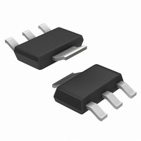
NCP1086ST-ADJT3 ON Semiconductor, NCP1086ST-ADJT3 Datasheet - Page 5

NCP1086ST-ADJT3
Manufacturer Part Number
NCP1086ST-ADJT3
Description
IC REG 1.5A ADJ VOLTAGE SOT223
Manufacturer
ON Semiconductor
Datasheet
1.NCP1086ST-ADJT3.pdf
(13 pages)
Specifications of NCP1086ST-ADJT3
Regulator Topology
Positive Adjustable
Voltage - Output
1.25 ~ 5.5 V
Voltage - Input
Up to 7V
Voltage - Dropout (typical)
1.05V @ 1.5A
Number Of Regulators
1
Current - Output
1.5A
Current - Limit (min)
1.6A
Operating Temperature
0°C ~ 70°C
Mounting Type
Surface Mount
Package / Case
SOT-223 (3 leads + Tab), SC-73, TO-261
Lead Free Status / RoHS Status
Contains lead / RoHS non-compliant
Other names
NCP1086ST-ADJT3OS
Available stocks
Company
Part Number
Manufacturer
Quantity
Price
Part Number:
NCP1086ST-ADJT3
Manufacturer:
ON/安森美
Quantity:
20 000
adjustable and 3.3 V output voltages at currents up to 1.5 A.
The regulator is protected against overcurrent conditions
and includes thermal shutdown.
transistor and requires an output capacitor for stability. A
detailed procedure for selecting this capacitor is included in
the Stability Considerations section.
Adjustable Operation
of 1.25 V to 5.5 V. An external resistor divider sets the
output voltage as shown in Figure 15. The regulator
maintains a fixed 1.25 V (typical) reference between the
output pin and the adjust pin.
The NCP1086 voltage regulator series provides
The NCP1086 series has a composite PNP−NPN output
The adjustable output device has an output voltage range
0.100
0.075
0.050
0.025
85
75
65
55
45
35
25
15
10
Figure 11. Ripple Rejection vs. Frequency
Figure 13. Load Regulation vs. Output Current
0
1
0
T
I
(V
V
C
OUT
CASE
RIPPLE
Adj
IN
− V
= 0.1 mF
= 6A
10
= 25°C
OUT
= 1.6V
2
(Adjustable Output)
= 3V)
(Adjustable Output)
PP
Frequency (Hz)
10
Output Current (A)
3
T
CASE
1.0
10
= 25°C
4
T
CASE
APPLICATIONS INFORMATION
10
= 125°C
5
T
CASE
http://onsemi.com
= 0°C
10
6
2.0
5
current to flow to ground. This current creates a voltage
across R2 that adds to the 1.25 V across R1 and sets the
overall output voltage. The adjust pin current (typically
50 mA) also flows through R2 and adds a small error that
should be taken into account if precise adjustment of V
is necessary.
pin current.
0.65
0.60
0.55
0.50
0.45
0.40
A resistor divider network R1 and R2 causes a fixed
The output voltage is set according to the formula:
The term I
85
75
65
55
45
35
25
15
1.0
10
Figure 14. Minimum Load Current vs V
1
V OUT + V REF
T
I
(V
V
OUT
CASE
RIPPLE
Figure 12. Ripple Rejection vs. Frequency
IN
Adj
2.0
− V
= 6A
10
= 25°C
× R2 represents the error added by the adjust
OUT
= 1.6V
2
= 3V)
(Adjustable Output)
3.0
(3.3 V Fixed Output)
PP
T
Frequency (Hz)
10
V
T
CASE
CASE
IN
C
3
R1 ) R2
− V
IN
4.0
= C
= 0°C
R1
= 25°C
OUT
OUt
10
(V)
= 22 mF Tantalum
4
) I Adj
5.0
T
CASE
10
6.0
5
IN
= 125°C
R2
− V
OUT
OUT
10
7.0
6


