NCP1086ST-ADJT3 ON Semiconductor, NCP1086ST-ADJT3 Datasheet - Page 8
NCP1086ST-ADJT3
Manufacturer Part Number
NCP1086ST-ADJT3
Description
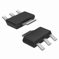
IC REG 1.5A ADJ VOLTAGE SOT223
Manufacturer
ON Semiconductor
Datasheet
1.NCP1086ST-ADJT3.pdf
(13 pages)
Specifications of NCP1086ST-ADJT3
Regulator Topology
Positive Adjustable
Voltage - Output
1.25 ~ 5.5 V
Voltage - Input
Up to 7V
Voltage - Dropout (typical)
1.05V @ 1.5A
Number Of Regulators
1
Current - Output
1.5A
Current - Limit (min)
1.6A
Operating Temperature
0°C ~ 70°C
Mounting Type
Surface Mount
Package / Case
SOT-223 (3 leads + Tab), SC-73, TO-261
Lead Free Status / RoHS Status
Contains lead / RoHS non-compliant
Other names
NCP1086ST-ADJT3OS
Available stocks
Company
Part Number
Manufacturer
Quantity
Price

Part Number:
NCP1086ST-ADJT3
Manufacturer:
ON/安森美
Quantity:
20 000


may be required for some applications. Thermal compound
should always be used with high current regulators such as
these.
following four factors:
1. Maximum Ambient Temperature T
2. Power dissipation P
3. Maximum junction temperature T
4. Thermal resistance junction to ambient R
dissipation are determined by the design while the
maximum junction temperature and the thermal resistance
depend on the manufacturer and the package type.
where:
V
V
I
I
package to improve the flow of heat away from the IC and
into the surrounding air.
P D(max) + { V IN(max) * V OUT(min) } I OUT(max) ) V IN(max) I Q
OUT(max)
Q
IN(max)
OUT(min)
The case is connected to V
The thermal characteristics of an IC depend on the
These four are related by the equation
The maximum ambient temperature and the power
The maximum power dissipation for a regulator is:
A heatsink effectively increases the surface area of the
is the maximum quiescent current at I
is the maximum input voltage,
is the maximum output current, for the application
is the minimum output voltage,
T J + T A ) P D
D
(W)
OUT
, and electrical isolation
R qJA
J
A
(°C)
OUT(max)
(°C)
qJA
.
(°C/W)
(eq. 1)
(eq. 2)
http://onsemi.com
8
outside environment has a thermal resistance. Like series
electrical resistances, these resistances are summed to
determine R
junction and the surrounding air.
1. Thermal Resistance of the junction to case, R
2. Thermal Resistance of the case to Heatsink, R
3. Thermal Resistance of the Heatsink to the ambient
result can be substituted in Equation 1.
regulator such as the NCP1086 the majority of the heat is
generated in the power transistor section. The value for
R
factors such as package type, heatsink interface (is an
insulator and thermal grease used?), and the contact area
between the heatsink and the package. Once these
calculations are complete, the maximum permissible value
of R
For further discussion on heatsink selection, see application
note
AND8036/D via our website at www.onsemi.com.
qSA
Each material in the heat flow path between the IC and the
These are connected by the equation:
The value for R
The value for R
qJA
(°C/W)
(°C/W)
air, R
depends on the heatsink type, while R
“Thermal
can be calculated and the proper heatsink selected.
qSA
qJA
R qJA + R qJC ) R qCS ) R qSA
(°C/W)
, the total thermal resistance between the
qJA
qJC
Management,”
is calculated using Equation 3 and the
is 3.5°C/W. For a high current
document
qCS
depends on
qJC
qCS
number
(eq. 3)
Related parts for NCP1086ST-ADJT3
Image
Part Number
Description
Manufacturer
Datasheet
Request
R

Part Number:
Description:
IC REG 1.5A 3.3V SOT223
Manufacturer:
ON Semiconductor
Datasheet:
Part Number:
Description:
IC REG 1.5A 3.3V SOT223
Manufacturer:
ON Semiconductor
Datasheet:
Part Number:
Description:
IC REG 1.5A ADJ VOLTAGE SOT223
Manufacturer:
ON Semiconductor
Datasheet:

Part Number:
Description:
ON Semiconductor [VOLTAGE REGULATOR]
Manufacturer:
ON Semiconductor
Datasheet:
Part Number:
Description:
357-036-542-201 CARDEDGE 36POS DL .156 BLK LOPRO
Manufacturer:
ON Semiconductor
Datasheet:
Part Number:
Description:
357-036-542-201 CARDEDGE 36POS DL .156 BLK LOPRO
Manufacturer:
ON Semiconductor
Datasheet:
Part Number:
Description:
357-036-542-201 CARDEDGE 36POS DL .156 BLK LOPRO
Manufacturer:
ON Semiconductor
Datasheet:
Part Number:
Description:
357-036-542-201 CARDEDGE 36POS DL .156 BLK LOPRO
Manufacturer:
ON Semiconductor
Datasheet:
Part Number:
Description:
357-036-542-201 CARDEDGE 36POS DL .156 BLK LOPRO
Manufacturer:
ON Semiconductor
Datasheet:
Part Number:
Description:
357-036-542-201 CARDEDGE 36POS DL .156 BLK LOPRO
Manufacturer:
ON Semiconductor
Datasheet:
Part Number:
Description:
357-036-542-201 CARDEDGE 36POS DL .156 BLK LOPRO
Manufacturer:
ON Semiconductor
Datasheet:
Part Number:
Description:
357-036-542-201 CARDEDGE 36POS DL .156 BLK LOPRO
Manufacturer:
ON Semiconductor
Datasheet:
Part Number:
Description:
357-036-542-201 CARDEDGE 36POS DL .156 BLK LOPRO
Manufacturer:
ON Semiconductor
Datasheet:
Part Number:
Description:
357-036-542-201 CARDEDGE 36POS DL .156 BLK LOPRO
Manufacturer:
ON Semiconductor
Datasheet: