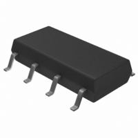
TISP61089BDR Bourns Inc., TISP61089BDR Datasheet - Page 6

TISP61089BDR
Manufacturer Part Number
TISP61089BDR
Description
SURGE SUPP SLIC PROG HV 8-SOP
Manufacturer
Bourns Inc.
Datasheet
1.TISP61089BDR-S.pdf
(20 pages)
Specifications of TISP61089BDR
Package / Case
8-SOIC (3.9mm Width)
Voltage - Breakover
*
Voltage - Off State
170V
Current - Peak Pulse (10 X 1000µs)
30A
Current - Hold (ih)
150mA
Number Of Elements
2
Capacitance
100pF
Applications
SLIC
Number Of Circuits
2
Voltage - Working
-100V
Voltage - Clamping
-112V
Technology
Mixed Technology
Breakover Current Ibo Max
6.5 A
Rated Repetitive Off-state Voltage Vdrm
170 V
Off-state Leakage Current @ Vdrm Idrm
0.005 mA
Holding Current (ih Max)
150 mA
Mounting Style
SMD/SMT
Power (watts)
-
Lead Free Status / RoHS Status
Lead free / RoHS Compliant
Available stocks
Company
Part Number
Manufacturer
Quantity
Price
Part Number:
TISP61089BDR
Manufacturer:
BOURNS/伯恩斯
Quantity:
20 000
Company:
Part Number:
TISP61089BDR-S
Manufacturer:
LITTLEFUSE
Quantity:
4 114
Company:
Part Number:
TISP61089BDR-S
Manufacturer:
Bourns Inc.
Quantity:
31 562
Part Number:
TISP61089BDR-S
Manufacturer:
BOURNS/伯恩斯
Quantity:
20 000
Specifications are subject to change without notice.
Customers should verify actual device performance in their specific applications.
Figure 4 shows a typical powering arrangement for a multi-supply rail SLIC. V BATL is a lower (smaller) voltage supply than V BATH . With supply
switch S1 in the position shown, the line driver amplifiers are powered between 0 V and V BATL . This mode minimizes the power consumption
for short loop transmission. For long loops and to generate ringing, the driver voltage is increased by operating S1 to connect V BATH . These
conditions are shown in Figure 5.
Conventional ringing is typically unbalanced ground or battery backed. To minimize the supply voltage required, most multi-rail SLICs use
balanced ringing as shown in Figure 5. The ringing has d.c., V
has a peak value, V
internal losses in the SLIC from ground, V
10 V. This makes a total, V
In some cases a trapezoidal a.c. ring signal is used. This would have a peak to r.m.s ratio (crest factor) of about 1.25, increasing the r.m.s. a.c.
ring level by 13 %. The d.c. ring voltage may be lowered for short loop applications.
OCTOBER 2000 - REVISED JULY 2008
Operation of Ringing SLICs using Multiple Negative Voltage Supply Rails
TISP61089B High Voltage Ringing SLIC Protector
SHORT LOOP
PKRING
BATH
, of 99 V. If the d.c. component was 20 V, then the total voltage swing needed would be 99 + 20 = 119 V. There are
0 V
V
BATL
, supply rail value of 119 + 10 = 129 V.
SLICG
LONG LOOP
Figure 4. SLIC with Voltage Supply Switching
LINE
, and the negative supply, V
Figure 5. Driver Supply Voltage Levels
APPLICATIONS INFORMATION
DRIVERS
LINE
DCRING
0 V
V
BATH
SLIC
, and a.c., V
V
DCRING
SUPPLY
SWITCH
SLICH
S1
. The sum of these two losses generally amounts to a total of
PKRING
V
V
PKRING
PKRING
, components. A 70 V r.m.s. a.c. sinusoidal ring signal
AI6XCC
0 V
V
V
BATL
BATH
/2
/2
RINGING
V
V
SLICH
SLICG
V
V
PKRING
PKRING
/2
/2
AI6XCD
V
BATH
0 V
V
BATH


