DLP-USB1232H DLP Design Inc, DLP-USB1232H Datasheet - Page 4
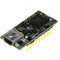
DLP-USB1232H
Manufacturer Part Number
DLP-USB1232H
Description
MODULE USB-TO-UART/FIFO HS 18DIP
Manufacturer
DLP Design Inc
Datasheet
1.DLP-USB1232H.pdf
(14 pages)
Specifications of DLP-USB1232H
Convert From (adapter End)
USB
Convert To (adapter End)
UART/FIFO
Features
2.0 High Speed USB
Interface Type
USB
Data Bus Width
8 bit
Operating Supply Voltage
4 V to 5.5 V
For Use With/related Products
Windows® Vista, 2000, XP, Mac
Lead Free Status / RoHS Status
Lead free / RoHS Compliant
Lead Free Status / RoHS Status
Lead free / RoHS Compliant, Lead free / RoHS Compliant
Other names
813-1026


2.0 PIN DESCRIPTIONS
This section describes the operation of the DLP-USB1232H pins. The function of the I/O pins is
determined by the configuration that is stored in the EEPROM connected to the FT2232H USB
IC.
The following table details the function of each pin for the specified mode. Note that the
convention used throughout this document for active low signals is the signal name followed by
a #. Pins marked ** default to tri-stated inputs with an internal 75K Ohm (approx) pull up
resistor to VCCIO (3.3V).
Rev. 1.3 (December 2009)
Pin #
18
16
17
13
15
14
11
12
2
5
4
3
7
Pin
Pin Name
ADBUS0
ADBUS1
ADBUS2
ADBUS3
ADBUS4
ADBUS5
ADBUS6
ADBUS7
ACBUS0
ACBUS1
ACBUS2
ACBUS3
ACBUS4
RXLED#
TXLED#
(RS232)
ASYNC
TXDEN
Serial
DCD#
DSR#
RTS#
CTS#
DTR#
RXD
TXD
RI#
Pin Functions For Each Supported Mode
245 FIFO
SIWUA
RXF#
TXE#
DLP-USB1232H
WR#
RD#
D0
D1
D2
D3
D4
D5
D6
D7
Channel A
4
WRSTB#
Bit-bang
RDSTB#
ASYNC
SIWUA
D0
D1
D2
D3
D4
D5
D6
D7
**
**
WRSTB#
Bit-bang
RDSTB#
SIWUA
SYNC
D6
D0
D1
D2
D3
D4
D5
D7
**
**
© DLP Design, Inc.
TMS/CS
GPIOH0
GPIOH1
GPIOH2
GPIOH3
GPIOH4
TCK/SK
GPIOL0
GPIOL1
GPIOL2
GPIOL3
MPSSE
TDI/DO
TDO/DI
SIWUA
Target
WR#
CPU
RD#
CS#
D0
D1
D2
D3
D4
D5
D6
D7
A0
Related parts for DLP-USB1232H
Image
Part Number
Description
Manufacturer
Datasheet
Request
R

Part Number:
Description:
Interface Modules & Development Tools Legacy USB Adapter
Manufacturer:
DLP Design Inc
Datasheet:

Part Number:
Description:
MODULE USB ADAPTER FOR FT2232D
Manufacturer:
DLP Design Inc
Datasheet:

Part Number:
Description:
MODULE USB-TO-FPGA TOOL W/MANUAL
Manufacturer:
DLP Design Inc
Datasheet:

Part Number:
Description:
Interface Modules & Development Tools RETRACTABLE USB CBL USB TO MINI USB
Manufacturer:
DLP Design Inc
Part Number:
Description:
Interface Modules & Development Tools USB FPGA Module w/ Xilinx XC3S400A
Manufacturer:
DLP Design Inc
Datasheet:

Part Number:
Description:
MODULE USB-TO-PARL FIFO 18-DIP
Manufacturer:
DLP Design Inc
Datasheet:

Part Number:
Description:
MODULE USB-TO-SRL UART 18-DIP
Manufacturer:
DLP Design Inc
Datasheet:

Part Number:
Description:
MODULE USB ADAPTR FOR FT2232D LP
Manufacturer:
DLP Design Inc
Datasheet:

Part Number:
Description:
MODULE USB-MCU FT245RL W/16F877A
Manufacturer:
DLP Design Inc
Datasheet:

Part Number:
Description:
MODULE USB-TO-FPGA TRAINING TOOL
Manufacturer:
DLP Design Inc
Datasheet:

Part Number:
Description:
MODULE USB-MCU FT232R W/18F2410
Manufacturer:
DLP Design Inc
Datasheet:

Part Number:
Description:
MODULE USB-MCU FT245RL W/SX48
Manufacturer:
DLP Design Inc
Datasheet:

Part Number:
Description:
MODULE USB-MCU FT2232D W/16F877A
Manufacturer:
DLP Design Inc
Datasheet:

Part Number:
Description:
MODULE USB-TO-FPGA SPARTAN3
Manufacturer:
DLP Design Inc
Datasheet:

Part Number:
Description:
MOD USB-MCU FT245RL W/18LF8722
Manufacturer:
DLP Design Inc
Datasheet: