NFR0300001008JAC00 Vishay, NFR0300001008JAC00 Datasheet - Page 5
NFR0300001008JAC00
Manufacturer Part Number
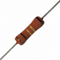
NFR0300001008JAC00
Description
RES 1.0 OHM 3W 5% MF FUSIBLE
Manufacturer
Vishay
Series
NFR03r
Datasheet
1.NFR0100006809JR500.pdf
(7 pages)
Specifications of NFR0300001008JAC00
Temperature Coefficient
±200ppm/°C
Resistance (ohms)
1
Power (watts)
3W
Composition
Metal Film
Features
Flame Proof, Fusible
Tolerance
±5%
Size / Dimension
0.209" Dia x 0.768" L (5.30mm x 19.50mm)
Lead Style
Through Hole
Package / Case
Axial
Resistance In Ohms
1.00
Case
Axial
Resistance
1ohm
Resistance Tolerance
± 5%
Power Rating
3W
Resistor Element Material
Metal Film
Resistor Case Style
Axial Leaded
No. Of Pins
2
Lead Free Status / RoHS Status
Lead free / RoHS Compliant
Height
-
Lead Free Status / RoHS Status
Lead free / RoHS Compliant, Lead free / RoHS Compliant
Other names
2306 210 13108
230621013108
5093FM1R000J08AFX
PPC1.0ETB
230621013108
5093FM1R000J08AFX
PPC1.0ETB


NFR03
FUSING CHARACTERISTIC
The resistors will fuse without the risk of fire and within an indicated range of overload. Fusing means that the resistive value of
the resistor increases at least 100 times.
TESTS AND REQUIREMENTS
Essentially all tests are carried out in accordance with the schedule of IEC 60115-1, category 55/155/56 (rated temperature range
- 55 to + 155 °C; damp heat, long term, 56 days) and along the lines of IEC 60068-2; “Recommended basic climatic and
mechanical robustness testing procedure for electronic components” and under standard atmosphere conditions according to
IEC 60068-1 subclause 5.3, unless otherwise specified. In some instances deviations from IEC applications were necessary for
our specified method.
Document Number: 30256
Revision: 06-Dec-07
Resistance Range
0.47 Ω - 10 Ω
10.1 Ω - 1 kΩ
PERFORMANCE
IEC
60115-1
CLAUSE
4.8
4.25.1
4.26
(°C)
Δ
T
METHOD
Hot spot temperature rise (ΔT) as a function
60068-2
180
160
140
120
100
80
60
40
20
TEST
IEC
0
0
-
-
-
0
Ø 0.80 mm Cu
0.5
Endurance at 70 °C
Accidental overload
of dissipated power
Temperature
coefficient
Hot Spot
1.0
TEST
P
For technical questions, contact: filmresistors.leaded@vishay.com
1.5
(W)
2.0
Fusible Power Metal Film Leaded
Overload of 5, 10, 16, 25, 40, 63
but the applied voltage shall not
and 100 times the rated power,
exceed four times the limiting
≥ 20 x maximum dissipation at 70 °C (Pn)
≥ 16 x maximum dissipation at 70 °C (Pn)
loaded with Pn or V
2.5
- 55 °C and + 155 °C
1.5 h ON; 0.5 h OFF
PROCEDURE
3.0
Between
1000 h;
voltage.
Power Overload
Resistors
max.
;
point) as a function of dissipated power at various leads
(°C)
Δ
T
Temperature rise (ΔT) at the lead end (soldering
100
80
60
40
20
0
NFR01
0
Ø 0.80 mm Cu
NFR01, NFR02, NFR03
0.5
lengths after mounting
PERMISSIBLE CHANGE (ΔR)
Solder Spot
1.0
Vishay BCcomponents
REQUIREMENTS
± (5 % R + 0.1 Ω)
Non-flammable
± 200 ppm/K
P
NFR02
1.5
(W)
Fusing Time
≤ 60 s
2.0
15 mm
2.5
20 mm
25 mm
www.vishay.com
NFR03
3.0
5
Related parts for NFR0300001008JAC00
Image
Part Number
Description
Manufacturer
Datasheet
Request
R

Part Number:
Description:
357-036-542-201 CARDEDGE 36POS DL .156 BLK LOPRO
Manufacturer:
Vishay
Datasheet:
Part Number:
Description:
357-036-542-201 CARDEDGE 36POS DL .156 BLK LOPRO
Manufacturer:
Vishay
Datasheet:
Part Number:
Description:
357-036-542-201 CARDEDGE 36POS DL .156 BLK LOPRO
Manufacturer:
Vishay
Datasheet:
Part Number:
Description:
357-036-542-201 CARDEDGE 36POS DL .156 BLK LOPRO
Manufacturer:
Vishay
Datasheet:
Part Number:
Description:
357-036-542-201 CARDEDGE 36POS DL .156 BLK LOPRO
Manufacturer:
Vishay
Datasheet:
Part Number:
Description:
357-036-542-201 CARDEDGE 36POS DL .156 BLK LOPRO
Manufacturer:
Vishay
Datasheet:
Part Number:
Description:
357-036-542-201 CARDEDGE 36POS DL .156 BLK LOPRO
Manufacturer:
Vishay
Datasheet:
Part Number:
Description:
357-036-542-201 CARDEDGE 36POS DL .156 BLK LOPRO
Manufacturer:
Vishay
Datasheet:
Part Number:
Description:
357-036-542-201 CARDEDGE 36POS DL .156 BLK LOPRO
Manufacturer:
Vishay
Datasheet:
Part Number:
Description:
357-036-542-201 CARDEDGE 36POS DL .156 BLK LOPRO
Manufacturer:
Vishay
Datasheet:
Part Number:
Description:
357-036-542-201 CARDEDGE 36POS DL .156 BLK LOPRO
Manufacturer:
Vishay
Datasheet:
Part Number:
Description:
357-036-542-201 CARDEDGE 36POS DL .156 BLK LOPRO
Manufacturer:
Vishay
Datasheet:
Part Number:
Description:
357-036-542-201 CARDEDGE 36POS DL .156 BLK LOPRO
Manufacturer:
Vishay
Datasheet:
Part Number:
Description:
357-036-542-201 CARDEDGE 36POS DL .156 BLK LOPRO
Manufacturer:
Vishay
Datasheet:
Part Number:
Description:
357-036-542-201 CARDEDGE 36POS DL .156 BLK LOPRO
Manufacturer:
Vishay
Datasheet: