E3C-C Omron, E3C-C Datasheet
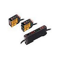
E3C-C
Specifications of E3C-C


Related parts for E3C-C


E3C-C Summary of contents
Page 1
... CSM_E3C_DS_E_7_1 Red light Infrared light Model E3C-S10 2M Emitter E3C-S10L 2M Receiver E3C-S10D 2M E3C-S50 2M Emitter E3C-S50L 2M 500 mm Receiver E3C-S50D 2M E3C-1 2M Emitter E3C- Receiver E3C-1D 2M E3C-2 2M Emitter E3C- Receiver E3C-2D 2M E3C-S20W 2M Emitter E3C-S20LW 2M Receiver E3C-S20DW 2M E3C-S30W 2M Emitter E3C-S30LW 2M Receiver E3C-S30DW 2M 300 mm E3C-S30T 2M Emitter E3C-S30LT 2M ...
Page 2
... Provided with the E3C-2. 2 Can be used with the E3C-DS10 Can be used with the E3C-S10 Can be used with the E3C-S50. Quantity Remarks 1 Provided with the E3C-A/C. 1 Can be used with the E3C-GE4. 1 Can be used with the E3C-GE4. Model --- E3C-A E3C-C Timer E3C-JC4P 2M Self diagnostic --- E3C-GE4 E3C 2 ...
Page 3
... Infrared LED (950 nm) 2 for 3 times each and Z directions IEC 60529 IP64 (Limited to indoor use) Instruction manual E3C E3C-1 E3C Opaque, 4-mm Opaque, 8-mm dia. min. dia. min. Emitter/Receiv- Emitter/Receiv- er 20° each er 15° ...
Page 4
... Stainless steel Brackets Connection Socket (PF113A) Accessories Instruction manual * The terminal pins are used for connection between amplifiers for synchronous operation. E3C VDC±10%, ripple (p-p max max. Load power supply voltage: 24 VDC max., load current: 100 mA max., NPN open collector output type (residual voltage max ...
Page 5
... X (mm) −100 −150 −200 Through-beam E3C-S30T/-S30W 200 Y 150 X 100 50 0 600 200 400 800 Sensing −50 distance X (mm) −100 −150 −200 Diffuse-reflective E3C-DS10 (Example OFF 30 Y Moving direction of object Optical 20 axis 120 200 160 −10 Sensing distance −20 X (mm) − ...
Page 6
... Diffuse-reflective E3C-DS10 (Example Moving direction of object OFF 30 Y Optical 20 axis 120 200 160 −10 Sensing distance −20 X (mm) −30 −40 Excess Gain vs. Set Distance E3C-S20W 100 Operating Level 1 0.7 0.5 0.3 0.1 0 100 200 300 400 500 Set distance (mm) E3C-DS5W 100 ...
Page 7
... OFF * For t in the timing chart, refer to Part Names/Selection Method on page 9. Operation * selector t t LIGHT ON Synchronous 9 inputs * DARK E3C-C only * 2. E3C-A/-C have SPDT contact output. (About terminal number, please refer to the connection section.) L-ON Light (LIGHT ON) indicator (red D-ON (DARK ON Switched with wiring. − ...
Page 8
... Receiver side (white) − (Note) and 50 mm max. on the Gate input Emitter side (red The E3C-A does not have a gate input function when the gate input 2-9 terminals are connected, H when they are 7 8 disconnected. 100 to 240 VAC Emitter/receiver Note: 1 ...
Page 9
... Operation selector Selector switch for response time Timer function setting switch Delay time setting switch Delay time adjuster E3C-C Timer function setting DARK (B) When select- ing ON delay DELAY (ON D sec DARK (B) When select- ing OFF de- DELAY lay (OFF D ...
Page 10
... H disconnected * power supply Timing chart Incident light No incident light − − E3C Settings --- DARK turns the output "H". LIGHT turns the output "H". The response time is set to 2 ms. The response time is set No-contact (Output output transistor) "H" (OFF) "L" ...
Page 11
... Emitter (Shield) Red Connection Socket The standard socket is the PF113A for the E3C-A and -C, and the PYF08A, PYF08M or PY08 for the E3C-GE4. Avoid using any other sockets since they may not satisfy the characteristics. (There will be no problem when the STABILITY indicator turns ON) Sensor Units ● ...
Page 12
... Dimensions Sensors Sensor Units E3C-S10 Emitter: E3C-S10L Receiver: E3C-S10D E3C-S50 Emitter: E3C-S50L Receiver: E3C-S50D E3C 3.5 Emitter: E3C-1L Lens 4 dia. Receiver: E3C-1D (A)* E3C Lens 8 dia. (A)* Emitter: E3C-2L * Mounting Bracket can be attached to side A. Receiver: E3C-2D Tolerance class IT16 applies to dimensions in this data sheet unless otherwise specified. ...
Page 13
... E3C-S20LW Receiver: E3C-S20DW E3C-S30W Emitter: E3C-S30LW Receiver: E3C-S30DW E3C-S30T 1.93-dia. shielded robotics cable with 1 conductor (Conductor cross section: 0.15 mm Standard length Emitter: E3C-S30LT Receiver: E3C-S30DT E3C-DS10 Receiver 2 2 dia. (receiver) 2,000 18 4.5 (white) 4 (6) 12.5 1.75-dia. shielded cable 2.5 with 1 conductor ± ...
Page 14
... Standard length 4 Emitter Receiver Lens 13 Optical axis ±1 R3 position 30 2.4-dia. shielded cable with 2 conductors (Conductor cross section: 0.3 mm Standard length Receiver 4 ±0.2 7 19.5 6 3.8 dia. 2.3 dia. 2.5 1.4 Emitter 2.8 4.6 R1.2 6.6 2 E3C 14 ...
Page 15
... Amplifier Units E3C-A Operation indicator (red) E3C-C 48 E3C-JC4P 3 2.5 E3C-GE4 Stability indicator (green) 27.2 Accessories (Order Separately) Mounting Brackets Refer to E39-L/F39-L/E39-S/E39-R for details. Connecting Sockets Refer to E39-L/F39-L/E39-S/E39-R for details. Stability indicator (green) Light indicator (red With Mounting Bracket Attached Light indicator Timer mode selector switch M2 ...
Page 16
... Please read and understand this catalog before purchasing the products. Please consult your OMRON representative if you have any questions or comments. WARRANTY OMRON's exclusive warranty is that the products are free from defects in materials and workmanship for a period of one year (or other period if specified) from date of sale by OMRON. OMRON MAKES NO WARRANTY OR REPRESENTATION, EXPRESS OR IMPLIED, REGARDING NON-INFRINGEMENT, MERCHANTABILITY, OR FITNESS FOR PARTICULAR PURPOSE OF THE PRODUCTS ...