E3C-C Omron, E3C-C Datasheet - Page 11
E3C-C
Manufacturer Part Number
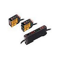
E3C-C
Description
AMPL PHOTO 100-240V 50/60HZ TIMR
Manufacturer
Omron
Series
E3Cr
Specifications of E3C-C
Amplifier Type
Standard
Voltage - Supply
100 V ~ 240 VAC
Output Type
Relay / NPN
Current - Supply
80mA
Mounting Type
Bracket Mount
Output
NPN
Light Source
Pulse Modulated Infrared LED
Connection
Separate Connector
Output Configuration
NPN
Output Current
80mA
Leaded Process Compatible
No
Peak Reflow Compatible (260 C)
No
Lead Free Status / RoHS Status
Lead free / RoHS Compliant
Lead Free Status / RoHS Status
Contains lead / RoHS non-compliant, Lead free / RoHS Compliant
Other names
E3CC


Safety Precautions
Refer to Warranty and Limitations of Liability.
This product is not designed or rated for ensuring
safety of persons either directly or indirectly.
Do not use it for such purposes.
Do not use the product in atmospheres or environments that exceed
product ratings.
● Wiring
Connection of E3C-JC4P Amplifier Unit and Sensor
Always run the shielded wires of the Emitter and Receiver separately.
Also, route the sensor cable along the cable grooves of the cover and
sensor and fix it with the cover.
Connection Socket
The standard socket is the PF113A for the E3C-A and -C, and the
PYF08A, PYF08M or PY08 for the E3C-GE4. Avoid using any other
sockets since they may not satisfy the characteristics. (There will be
no problem when the STABILITY indicator turns ON)
● Wiring
Extension Cable
• The extension distance of the sensor connection cable should be
• The strip-off length of the core in the connection cable should be 20
• Use independent shielded wires for the Emitter and Receiver.
within 10 m.
mm max. on the Receiver side and 50 mm max. on the Emitter side,
and the core should be as short as possible. Avoid using the joint
terminal and connector.
Using a common shielded wire can cause a malfunction.
Receiver
Emitter
Amplifier Units
Sensor Units
Precautions for Correct Use
(Shield) Red
White (Shield)
20 mm max.
WARNING
Socket
Extension Cable
Through-beam
Reflective model
● Others
When the E3C is used in a place where high-frequency noise will be
generated, e.g. ultrasonic welder, grounding the 0-V terminal (on the
shield side of the connection cable) of the Receiver may avoid a
malfunction caused by induction.
Model
E3C-S10
E3C-1
E3C-2
E3C-S50
E3C-S20W
E3C-S30T
E3C-S30W
Model
E3C-DS10
E3C-DS10T
E3C-VS1G
E3C-VS3R
E3C-LS3R
E3C-DS5W
E3C-VS7R
E3C-VM35R
Cable
Cable
2.4 dia.
Polyethylene insulation shield
Round cable
Vinyl insulation shield round cable
Vinyl insulation shield round cable
(robot cable)
Vinyl insulation shielded parallel ca-
ble
Vinyl insulation shielded parallel ca-
ble
2.4
1.7 dia.
1.8 dia.
12-conductor, 0.18 dia.
30-conductor, 0.08 dia.
12-conductor, 0.18 dia.
7-conductor, 0.18 dia.
12-conductor, 0.18 dia.
Specified cable
Specified cable
4.3
Shield
White (polyethylene)
Sheath
Shield
Polyethylene
Conductor
Sheath
Shield
Polyethylene
Conductor
Sheath
Shield
Polyethylene
Conductor
Conductor
Sheath
Internal
sheath
Shield
Polyethylene
1-conductor shield/
vinyl wire, conduc-
tor cross section:
0.3 mm
1-conductor shield/
vinyl wire, conduc-
tor cross section:
0.3 mm
When there is no1-
conductor shielded,
vinyl cable (parallel
wire), use two 1-
conductor shielded,
vinyl wires.
When there is no1-
conductor shielded,
vinyl cable (parallel
wire), use two 1-
conductor shielded,
vinyl wires.
Gray (vinyl sheath)
Replacement
Replacement
cable
cable
2
2
min.
min.
Shield
E3C
White
(vinyl)
11
Related parts for E3C-C
Image
Part Number
Description
Manufacturer
Datasheet
Request
R

Part Number:
Description:
EMITTER COMPONENT OF E3C-S20W
Manufacturer:
Omron
Datasheet:
Part Number:
Description:
AMP EXTERNL-INPT NPN-OUTPT CONN
Manufacturer:
Omron
Datasheet:
Part Number:
Description:
AMP TWIN-OUTPT NPN-OUTPUT W/CONN
Manufacturer:
Omron
Datasheet:
Part Number:
Description:
AMP TWIN-OUTPT PNP-OUTPT W/CONN
Manufacturer:
Omron
Datasheet:
Part Number:
Description:
AMP EXTRNL-INPT PNP-OUTPT W/CONN
Manufacturer:
Omron
Datasheet:
Part Number:
Description:
AMP ATC LASER TYPE NPN-OUTPUT
Manufacturer:
Omron
Datasheet:
Part Number:
Description:
AMP ATC LASER TYPE PNP-OUTPUT
Manufacturer:
Omron
Datasheet:
Part Number:
Description:
AMP ATC LASER NPN-OUTPUT W/CONN
Manufacturer:
Omron
Datasheet:
Part Number:
Description:
AMP ATC LASER PNP-OUTPUT W/CONN
Manufacturer:
Omron
Datasheet:
Part Number:
Description:
AMP ANALOG LASER TYPE NPN-OUTPUT
Manufacturer:
Omron
Datasheet:

Part Number:
Description:
PES AMP SLIM DIN MOUNT
Manufacturer:
Omron
Datasheet:

Part Number:
Description:
G6S-2GLow Signal Relay
Manufacturer:
Omron Corporation
Datasheet:
Part Number:
Description:
Compact, Low-cost, SSR Switching 5 to 20 A
Manufacturer:
Omron Corporation
Datasheet: