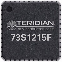
73S1215F-68IM/F Maxim Integrated Products, 73S1215F-68IM/F Datasheet - Page 43

73S1215F-68IM/F
Manufacturer Part Number
73S1215F-68IM/F
Description
IC SMART CARD READER 68-QFN
Manufacturer
Maxim Integrated Products
Datasheet
1.73S1209F-44IMF.pdf
(93 pages)
Specifications of 73S1215F-68IM/F
Core Processor
80515
Core Size
8-Bit
Speed
24MHz
Connectivity
I²C, SmartCard, UART/USART, USB
Peripherals
LED, POR, WDT
Number Of I /o
9
Program Memory Size
64KB (64K x 8)
Program Memory Type
FLASH
Ram Size
2K x 8
Voltage - Supply (vcc/vdd)
2.7 V ~ 5.5 V
Oscillator Type
Internal
Operating Temperature
-40°C ~ 85°C
Package / Case
*
Processor Series
1215x
Core
80515
Data Bus Width
8 bit
Data Ram Size
2 KB
Interface Type
UART, I2C
Maximum Clock Frequency
24 MHz
Number Of Programmable I/os
9
Number Of Timers
3
Operating Supply Voltage
2.7 V to 3.6 V / 4.75 V to 5.5 V
Maximum Operating Temperature
+ 85 C
Mounting Style
SMD/SMT
3rd Party Development Tools
PK51, CA51, A51, ULINK2
Development Tools By Supplier
73S1215F-EB, 73S1215F-EB-Lite, 73S1215F-IM44 DK, 73S1215F-IM44 EB, 73S1215F-IM68 DK, 73S1215F-IM68 EB
Minimum Operating Temperature
- 40 C
Lead Free Status / RoHS Status
Lead free / RoHS Compliant
Eeprom Size
-
Data Converters
-
Lead Free Status / Rohs Status
Details
Available stocks
Company
Part Number
Manufacturer
Quantity
Price
Company:
Part Number:
73S1215F-68IM/F
Manufacturer:
Maxim
Quantity:
240
UG_12xxF_016
The USB interface contains four endpoints, which are defined as follows:
1. Endpoint 0 for the control transfer
2. Endpoint 1 IN for the Bulk transfer
3. Endpoint 1 OUT for the Bulk transfer
4. Endpoint 2 IN for the interrupt transfer
The Low-level API handles all Endpoint 0 (control endpoint) communications; thus PC driver enumeration
takes place during the device reset time and is transparent to an application. An application can be
written to monitor this reset signal to determine when it can start sending Endpoint 1 IN and/or Endpoint
2 IN packets to the host or to expect Endpoint 1 OUT packets from the host. (References to
transmission direction (IN/OUT) are relative to the host.)
USB_Init()
This function will activate the USB interface and ALL Endpoints will be ACTIVE. Endpoint 0 gets device
descriptor requests and will return the device descriptor. Endpoint 0 gets configuration descriptor
Rev. 1.50
Purpose
Synopsis
Parameters
Return Codes None.
Configure the USB interface during the reset procedure. The descriptors (device,
configuration, endpoint, interface and string) used in future enumeration requests are
configured. When leaving this function, the USB interface is ready to answer any
enumeration request.
Void USB_Init (
struct USB_Init_t
{
};
The Device, Config, CCID, Strings and LangID structures are described at the end of
this function description.
pUSB: Input parameter
Specifies the Device, Configuration, Endpoints, Interfaces and String Descriptors
defining the USB interface.
pLangID: Input parameter
Specifies the Language ID codes String Descriptor.
pRESET: Input parameter
Specifies a pointer to the function to call when RESET signaling has occurred on the
USB bus.
pSUSPEND: Input parameter
Specifies a pointer to the function to call when SUSPEND signaling has occurred on
the USB bus.
pRESUME: Input parameter
Specifies a pointer to the function to call when RESUME signaling has occurred on
the USB bus.
IN struct USB_Init_t *pUSB,
IN struct USB_LangID_t *pLangID,
IN void (*pRESET) (),
IN void (*pSUSPEND) (),
IN void (*pRESUME) () );
struct USB_Device_t
struct USB_Config_t
struct USB_CCID_t
struct USB_Strings_t
Device;
Config;
CCID;
Strings;
73S12xxF Software User Guide
43


