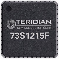
73S1215F-68IM/F Maxim Integrated Products, 73S1215F-68IM/F Datasheet - Page 60

73S1215F-68IM/F
Manufacturer Part Number
73S1215F-68IM/F
Description
IC SMART CARD READER 68-QFN
Manufacturer
Maxim Integrated Products
Datasheet
1.73S1209F-44IMF.pdf
(93 pages)
Specifications of 73S1215F-68IM/F
Core Processor
80515
Core Size
8-Bit
Speed
24MHz
Connectivity
I²C, SmartCard, UART/USART, USB
Peripherals
LED, POR, WDT
Number Of I /o
9
Program Memory Size
64KB (64K x 8)
Program Memory Type
FLASH
Ram Size
2K x 8
Voltage - Supply (vcc/vdd)
2.7 V ~ 5.5 V
Oscillator Type
Internal
Operating Temperature
-40°C ~ 85°C
Package / Case
*
Processor Series
1215x
Core
80515
Data Bus Width
8 bit
Data Ram Size
2 KB
Interface Type
UART, I2C
Maximum Clock Frequency
24 MHz
Number Of Programmable I/os
9
Number Of Timers
3
Operating Supply Voltage
2.7 V to 3.6 V / 4.75 V to 5.5 V
Maximum Operating Temperature
+ 85 C
Mounting Style
SMD/SMT
3rd Party Development Tools
PK51, CA51, A51, ULINK2
Development Tools By Supplier
73S1215F-EB, 73S1215F-EB-Lite, 73S1215F-IM44 DK, 73S1215F-IM44 EB, 73S1215F-IM68 DK, 73S1215F-IM68 EB
Minimum Operating Temperature
- 40 C
Lead Free Status / RoHS Status
Lead free / RoHS Compliant
Eeprom Size
-
Data Converters
-
Lead Free Status / Rohs Status
Details
Available stocks
Company
Part Number
Manufacturer
Quantity
Price
Company:
Part Number:
73S1215F-68IM/F
Manufacturer:
Maxim
Quantity:
240
73S12xxF Software User Guide
USER_IO_Config()
USER_IO_Read()
USER_IO_Write()
4.2.14 External Interrupts API – Available with all 73S12xxF Devices
This API allows direct access to the two external interrupt pins (EXT3 and EXT2). These two interrupts
are only available as edge (falling/negative or rising/positive) sensitive. The API includes:
•
•
•
•
INT2_Config()
60
Purpose
Synopsis
Parameters
Return Codes None.
Purpose
Synopsis
Parameters
Return Codes None.
Purpose
Synopsis
Parameters
Return Codes None.
INT2_Config()
INT2_Read()
INT3_Config()
INT3_Read()
Purpose
Synopsis
(page 61)
(page 61)
(page 60)
(page 61)
Configure the direction for the USER IO pins.
void USER_IO_ Config ( Unsigned char usrsrc, Unsigned char dir )
usrsrc: Input parameter
Corresponding USR pins to be configured as Input or Output. USRIO 0 through 7
will be configured according to the Dir parameter below.
Dir: Input parameter
Direction value (1=input, 0=output) for the selected pins.
Read the value of the USER IO pins.
void USER_IO_Read ( OUT char *user_dir, OUT char *user_data );
User_dir: Output parameter
Direction value (1=input, 0=output) for the selected pins.
User_data: Output parameter
Value of the corresponding USER IO pins. All outputs will reflect the last value
written.
Write values to selected USER IO pins.
Void USER_IO_Write ( IN char cUserIO, IN char cUserIOselect );
cUserIO: Input parameter
Values to write to selected USER IO pins.
cUserIOselect: Input parameter
configured as an output.
Configure External Interrupt 2.
void INT2_Config ( Unsigned char Enable, Unsigned char Polarity );
A ‘1’ in the corresponding bit will enable writing to that USR pin provided it is
UG_12xxF_016
Rev. 1.50


