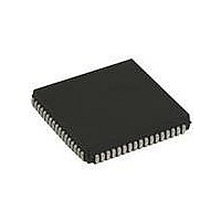
ST16C654IJ68-F Exar Corporation, ST16C654IJ68-F Datasheet - Page 13

ST16C654IJ68-F
Manufacturer Part Number
ST16C654IJ68-F
Description
IC UART FIFO 64B QUAD 68PLCC
Manufacturer
Exar Corporation
Datasheet
1.ST16C654CJ68-F.pdf
(51 pages)
Specifications of ST16C654IJ68-F
Number Of Channels
4, QUART
Package / Case
68-LCC (J-Lead)
Features
*
Fifo's
64 Byte
Protocol
RS232
Voltage - Supply
2.97 V ~ 5.5 V
With Auto Flow Control
Yes
With Irda Encoder/decoder
Yes
With False Start Bit Detection
Yes
With Modem Control
Yes
With Cmos
Yes
Mounting Type
Surface Mount
Data Rate
1.5 Mbps
Supply Current
6 mA
Maximum Operating Temperature
+ 85 C
Minimum Operating Temperature
- 40 C
Mounting Style
SMD/SMT
No. Of Channels
4
Uart Features
Infrared (IrDA) Encoder/Decoder
Supply Voltage Range
2.97V To 5.5V
Operating Temperature Range
-40°C To +85°C
Digital Ic Case Style
PLCC
Rohs Compliant
Yes
Lead Free Status / RoHS Status
Lead free / RoHS Compliant
Lead Free Status / RoHS Status
Lead free / RoHS Compliant, Lead free / RoHS Compliant
Other names
1016-1272
Available stocks
Company
Part Number
Manufacturer
Quantity
Price
Company:
Part Number:
ST16C654IJ68-F
Manufacturer:
Exar Corporation
Quantity:
135
Company:
Part Number:
ST16C654IJ68-F
Manufacturer:
MICRONAS
Quantity:
49
Company:
Part Number:
ST16C654IJ68-F
Manufacturer:
Exar Corporation
Quantity:
10 000
xr
REV. 5.0.2
Table 6 shows the standard data rates available with a 14.7456 MHz crystal or external clock at 16X sampling
rate. When using a non-standard frequency crystal or external clock, the divisor value can be calculated for
DLL/DLM with the following equation.
The transmitter section comprises of an 8-bit Transmit Shift Register (TSR) and 64 bytes of FIFO which
includes a byte-wide Transmit Holding Register (THR). TSR shifts out every data bit with the 16X internal
clock. A bit time is 16 clock periods. The transmitter sends the start-bit followed by the number of data bits,
inserts the proper parity-bit if enabled, and adds the stop-bit(s). The status of the FIFO and TSR are reported in
the Line Status Register (LSR bit-5 and bit-6).
The transmit holding register is an 8-bit register providing a data interface to the host processor. The host
writes transmit data byte to the THR to be converted into a serial data stream including start-bit, data bits,
parity-bit and stop-bit(s). The least-significant-bit (Bit-0) becomes first data bit to go out. The THR is the input
register to the transmit FIFO of 64 bytes when FIFO operation is enabled by FCR bit-0. Every time a write
operation is made to the THR, the FIFO data pointer is automatically bumped to the next sequential data
location.
O
2.9
2.9.1
UTPUT
MCR Bit-7=1
230.4k
115.2k
19.2k
38.4k
57.6k
1200
2400
4800
9600
100
600
Data Rate
Transmitter
Transmit Holding Register (THR) - Write Only
F
T
IGURE
ABLE
XTAL1
XTAL2
divisor (decimal) = (XTAL1 clock frequency / prescaler) / (serial data rate x 16)
O
UTPUT
6. B
6: T
MCR Bit-7=0
(D
153.6k
230.4k
460.8k
921.6k
EFAULT
19.2k
38.4k
76.8k
2400
4800
9600
YPICAL DATA RATES WITH A
AUD
400
Data Rate
R
Crystal
Buffer
)
Osc/
ATE
G
Clock (Decimal)
D
ENERATOR AND
IVISOR FOR
2304
384
192
96
48
24
12
6
4
2
1
Divide by 4
Divide by 1
Prescaler
Prescaler
16x
14.7456 MH
P
D
13
RESCALER
IVISOR FOR
Clock (HEX)
MCR Bit-7=0
MCR Bit-7=1
2.97V TO 5.5V QUAD UART WITH 64-BYTE FIFO
(default)
900
180
C0
0C
60
30
18
06
04
02
01
Z CRYSTAL OR EXTERNAL CLOCK
16x
Baud Rate
DLL and DLM
Generator
Registers
Logic
V
ALUE
P
ROGRAM
DLM
09
01
00
00
00
00
00
00
00
00
00
(HEX)
Rate Clock to
Transmitter
Sampling
16X
V
ALUE
P
ROGRAM
DLL
C0
0C
00
80
60
30
18
06
04
02
01
(HEX)
ST16C654/654D
D
E
ATA
RROR
0
0
0
0
0
0
0
0
0
0
0
R
ATE
(%)


