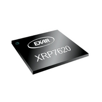
XRP7620IH-F Exar Corporation, XRP7620IH-F Datasheet

XRP7620IH-F
Specifications of XRP7620IH-F
Available stocks
Related parts for XRP7620IH-F
XRP7620IH-F Summary of contents
Page 1
... The XRP7620 is designed to operate from a single cell lithium-ion battery or fixed 3.3V or 5.0V power rails and is available in a RoHS compliant, “green”/halogen free space saving 8-pin 2mmx3mm DFN package. TYPICAL APPLICATION DIAGRAM Exar Corporation 48720 Kato Road, Fremont CA 94538, USA ...
Page 2
... LED Current Matching Line Regulation Current DAC Resolution Current for DAC=000000 Current for DAC=000001 Maximum LED Current DAC=111111 Maximum Current Change Settling Time Current Source Dropout Voltage Shutdown Supply Current Shutdown Supply Current Thermal Shutdown Die Temperature © 2009 Exar Corporation ...
Page 3
... Capacitive Load for each Bus Line Startup Time after UVLO clears Note 1: All parameters tested at T =25 °C. Specifications over temperature are guaranteed by design. A Note 2: LED current matching is calculated by this equation: − Where I × LED AVG 100 % I AVG © 2009 Exar Corporation ...
Page 4
... Note 4: Guaranteed by design. Note total capacitance of one bus line in pF. t Note 6: I ≤6mA. Cb =total capacitance of one bus line in pF. t SINK Note 7: Input filters on the SDA and SCL inputs suppress noise spikes less than 50ns. BLOCK DIAGRAM PIN ASSIGNEMENT © 2009 Exar Corporation ...
Page 5
... LED3 6 LED2 7 LED1 8 ORDERING INFORMATION Temperature Part Number Range XRP7620IH-F -40°C≤T ≤+100°C J XRP7620IHTR-F -40°C≤T ≤+100°C J XRP7620EVB XRP7620 Evaluation Board “YY” = Year – “WW” = Work Week – “F”= Green/Halogen Free Package - “X” = Lot Number XRP7620 may be ordered with alternative I © ...
Page 6
... Typical Performance Characteristics All data taken 2.7V to 5.5V Information/Theory of Operation section of this datasheet SDA SCL 20mA/div LED Fig. 5: LED Current Change Settling Time From 0.5mA to 31.5mA Fig. 7: SDA, SCL Timeout for Shutdown Fig. 9: Line Regulation DAC = 101000 (20mA) © 2009 Exar Corporation ...
Page 7
... Fig. 11: Line Regulation @ T DAC = 111100 (30mA) Fig. 13: Line Regulation @ T DAC = 111100 (30mA) Fig. 15: Line Regulation @ T DAC = 001010 (5mA) © 2009 Exar Corporation Fig. 12: Line Regulation @ - 7/ -40 A DAC = 111100 (30mA) o Fig. 14: Line Regulation @ DAC = 001010 (5mA) o Fig. 16: Line Regulation @ DAC = 001010 (5mA) ...
Page 8
... Putting 1 (logic high) will enable the driver and putting 0 (logic low) will disable the driver. Status register bits B1 and B0 These bits are the readback bits. Their values are 0 for normal operations. temperature is detected, undervoltage is detected, B0=1. threshold is approximately 2.4V. © 2009 Exar Corporation ...
Page 9
... SDA and SCL lines low for a minimum of typically 90ms. This puts a zero in bit 7 and bit 6 of the status register, which in turn will reset all bits of all registers. After any shutdown, the part can only be restarted 2 through the I C bus. © 2009 Exar Corporation ...
Page 10
... PACKAGE SPECIFICATION 8- PIN DFN © 2009 Exar Corporation 10/ Rev. 1.0.0 ...
Page 11
... While the information in this publication has been carefully checked; no responsibility, however, is assumed for inaccuracies. EXAR Corporation does not recommend the use of any of its products in life support applications where the failure or malfunction of the product can reasonably be expected to cause failure of the life support system or to significantly affect its safety or effectiveness. Products are not authorized for use in such applications unless EXAR Corporation receives, in writing, assurances to its satisfaction that: (a) the risk of injury or damage has been minimized ...


