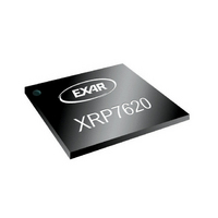
XRP7620IH-F Exar Corporation, XRP7620IH-F Datasheet - Page 8

XRP7620IH-F
Manufacturer Part Number
XRP7620IH-F
Description
IC LED SINK DVR I2C 4CH 8DFN
Manufacturer
Exar Corporation
Type
Backlight, RGBA, RGBWr
Specifications of XRP7620IH-F
Package / Case
8-VFDFN Exposed Pad
Number Of Outputs
4
Internal Driver
Yes
Type - Primary
Backlight, General Purpose
Type - Secondary
RGBA, RGBW
Frequency
400kHz
Voltage - Supply
2.7 V ~ 5.5 V
Mounting Type
Surface Mount
Current - Output / Channel
31.5mA
Internal Switch(s)
Yes
Efficiency
*
Low Level Output Current
31.5 mA
Operating Supply Voltage
2.5 V to 5.5 V
Maximum Supply Current
31.5 mA
Maximum Operating Temperature
+ 100 C
Mounting Style
SMD/SMT
Minimum Operating Temperature
- 40 C
Lead Free Status / RoHS Status
Lead free / RoHS Compliant
For Use With
1016-1340 - EVAL BOARD FOR XRP7620
Voltage - Output
-
Operating Temperature
-
Topology
-
Lead Free Status / Rohs Status
Lead free / RoHS Compliant
Other names
1016-1341
Available stocks
Company
Part Number
Manufacturer
Quantity
Price
Part Number:
XRP7620IH-F
Manufacturer:
EXAR/艾科嘉
Quantity:
20 000
THEORY OF OPERATION
I
The XRP7620 has five data registers which can
be
interface. The first register is a status register
which has two bits used for shutdown/power
up options, 4 bits used for individual LED
ON/OFF control, one bit for over-temperature
readback and one bit for undervoltage lockout
readback. The next four registers are used to
set the brightness levels of the four LEDs.
Status Register
Status register bits B7 and B6
The following table defines the states for bits
B7 and B6 of the STATUS register. They are
used to put the XRP7620 into shutdown,
standby, or active mode.
Status register bits B5-B2
These bits are to control the LED On/Off
individually. Putting 1 (logic high) will enable
the driver and putting 0 (logic low) will disable
the driver.
Status register bits B1 and B0
These bits are the readback bits. Their values
are
temperature
undervoltage is detected, B0=1.
threshold is approximately 2.4V.
© 2009 Exar Corporation
Status WZ
LED1
LED2
LED3
LED4
2
WZ
C
0
0
1
1
Table 2: XRP7620 Status Register Bits B7 and B6
SERIAL INTERFACE
programmed
0
WP
B7
D5
D5
D5
D5
0
1
0
1
Table 1: XRP7620 I
for
Shutdown and reset
registers to 00000000
Shutdown
Keeps registers contents
Standby
Keeps registers contents
Active
WP
B6
D4
D4
D4
D4
normal
is
LED4 LED3 LED2 LED1 OVT
B5
D3
D3
D3
D3
State
detected,
serially
B4
D2
D2
D2
D2
2
operations.
C Register Bit Map
B3
D1
D1
D1
D1
through
B1=1,
4
4
Active
30µA
0µA
0µA
-
-
B2
D0
D0
D0
D0
I
C
C
Q
h
h
a
a
LED Driver
If
The UVL
B1
n
n
the
-
-
-
-
and
n
n
Off
Off
Off
On
e
e
over-
l
l
UVL
B0
I²C
-
-
-
-
A
A
If
d
d
j
j
8/11
u
u
s
s
t
t
a
a
LED Registers (x4)
LED register bits B7-B2
In LED registers bits B7, B6, B5, B4, B3 and
B2 represent the DAC codes D5-D0 used to set
the LED current in the four LEDs, and B1 and
B0 are not used. The following table lists the
DAC codes and the corresponding current for
each channel in mA:
b
b
l
l
000000
000001
000010
000011
000100
000101
000110
000111
001000
001001
001010
001011
001100
001101
001110
001111
010000
010001
010010
010011
010100
010101
010110
010111
011000
011001
011010
011011
011100
011101
011110
011111
B7-B2
e
e
C
C
u
u
r
r
r
Table 3: LED Current DAC Settings
r
e
e
n
n
Current mA
t
t
I
I
10.0
10.5
11.0
11.5
12.0
12.5
13.0
13.5
14.0
14.5
15.0
15.5
0.5
1.0
1.5
2.0
2.5
3.0
3.5
4.0
4.5
5.0
5.5
6.0
6.5
7.0
7.5
8.0
8.5
9.0
9.5
2
2
0
C
C
C
C
o
o
n
n
t
t
r
r
100000
100001
100010
100011
100100
100101
100110
100111
101000
101001
101010
101011
101100
101101
101110
101111
110000
110001
110010
110011
110100
110101
110110
110111
111000
111001
111010
111011
111100
111101
111110
111111
B7-B2
o
o
l
l
l
l
e
e
d
d
X
X
L
L
R
R
E
E
Current mA
D
D
P
P
Rev. 1.0.0
7
7
D
16.0
16.5
17.0
17.5
18.0
18.5
19.0
19.5
20.0
20.5
21.0
21.5
22.0
22.5
23.0
23.5
24.0
24.5
25.0
25.5
26.0
26.5
27.0
27.5
28.0
28.5
29.0
29.5
30.0
30.5
31.0
31.5
D
6
6
r
r
i
i
2
v
2
v
e
e
0
0
r
r


