CP2501EK Silicon Laboratories Inc, CP2501EK Datasheet - Page 2
CP2501EK
Manufacturer Part Number
CP2501EK
Description
KIT EVALUATION CP2501
Manufacturer
Silicon Laboratories Inc
Datasheets
1.CP2501DK.pdf
(2 pages)
2.CP2501DK.pdf
(30 pages)
3.CP2501DK.pdf
(1 pages)
4.CP2501DK.pdf
(2 pages)
5.CP2501EK.pdf
(10 pages)
6.CP2501EK.pdf
(1 pages)
Specifications of CP2501EK
Main Purpose
Interface, Touch Screen Controller
Embedded
Yes, MCU, 8-Bit
Utilized Ic / Part
CP2501
Primary Attributes
Evaluation Board with Glass Sensor (Laminated Glass Lens)
Secondary Attributes
SPI, SMBus, or UART Interface
Interface Type
USB, I2C, SPI, UART
Operating Voltage
3.3 V
Data Bus Width
16 bit
Maximum Operating Temperature
+ 85 C
Minimum Operating Temperature
- 40 C
For Use With/related Products
CP2501, C8051F700
Lead Free Status / RoHS Status
Lead free / RoHS Compliant
Other names
336-1989


CP2501-EK
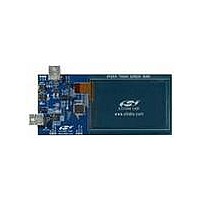
3. Hardware Overview
The CP2501 evaluation board has three main sections. The bottom-left side of the board includes the CP2501 and
the USB interface. The right half of the board includes the indium-tin oxide (ITO) touch screen and the touch-
screen sensing IC, which is a Silicon Labs C8051F700 MCU. The top-left of the board includes the programming/
debug interface for both devices.
To connect the board to a PC, connect one end of the USB cable to the bottom-left USB connector and the other
end to Windows PC. Ensure that a shorting block is placed on the J3 shorting block header. This connects the
power supply pins of the CP2501and the C8051F700 pins together and powers the entire evaluation board.
Two mechanical switches, GPIO2 and GPIO3, are connected to both the CP2501 and C8051F700. These
switches are used as the left-mouse button and the right-mouse button when the evaluation board is operating in
USB mouse mode.
To download new firmware to the CP2501 through the Silicon Labs IDE, connect a USB cable to the Debug USB
connector which is located on the top-side of the board. The firmware is also updateable using the CP2501 Boot
loader which is described in Section 7. If a shorting block is placed on the J2 header, the C8051F700 is powered
from the Debug USB connector.
The J1 header selects which device (CP2501 or C8051F700) is connected to the programming/debug circuitry.
For the CP2501, connect C2CK_DBG to C2CK_2501 and C2D_DBG to C2D_2501. For the C8051F700, connect
C2CK_DBG to C2CK_F700 and C2D_DBG to C2D_F700.
2
CP2501
GPIO3
GPIO2
PWR
J3
VDD_F700
VDD_2501
DS1
DEBUG
D5
P2
PWR
DEBUG
Debug
Figure 2. CP2501 Evaluation Board Hardware Overview
U2
P3
U3
D3
RUN/STOP
DS2
BRIDGE
CP2501
GPIO0
D4
www.silabs.com
SILICON LABS
J2
J1
SENSING
F700
U1
Rev. 0.1
CP2501 TOUCH SCREEN DEMO
Touch Screen
www.silabs.com
SILICON LABS
Related parts for CP2501EK
Image
Part Number
Description
Manufacturer
Datasheet
Request
R

Part Number:
Description:
IC TOUCH SCREEN USB BRIDGE 32QFN
Manufacturer:
Silicon Laboratories Inc
Datasheet:
Part Number:
Description:
Microcontrollers (MCU) Touch screen USB Bridge
Manufacturer:
Silicon Laboratories Inc
Part Number:
Description:
SMD/C°/SINGLE-ENDED OUTPUT SILICON OSCILLATOR
Manufacturer:
Silicon Laboratories Inc
Part Number:
Description:
Manufacturer:
Silicon Laboratories Inc
Datasheet:
Part Number:
Description:
N/A N/A/SI4010 AES KEYFOB DEMO WITH LCD RX
Manufacturer:
Silicon Laboratories Inc
Datasheet:
Part Number:
Description:
N/A N/A/SI4010 SIMPLIFIED KEY FOB DEMO WITH LED RX
Manufacturer:
Silicon Laboratories Inc
Datasheet:
Part Number:
Description:
N/A/-40 TO 85 OC/EZLINK MODULE; F930/4432 HIGH BAND (REV E/B1)
Manufacturer:
Silicon Laboratories Inc
Part Number:
Description:
EZLink Module; F930/4432 Low Band (rev e/B1)
Manufacturer:
Silicon Laboratories Inc
Part Number:
Description:
I°/4460 10 DBM RADIO TEST CARD 434 MHZ
Manufacturer:
Silicon Laboratories Inc
Part Number:
Description:
I°/4461 14 DBM RADIO TEST CARD 868 MHZ
Manufacturer:
Silicon Laboratories Inc
Part Number:
Description:
I°/4463 20 DBM RFSWITCH RADIO TEST CARD 460 MHZ
Manufacturer:
Silicon Laboratories Inc
Part Number:
Description:
I°/4463 20 DBM RADIO TEST CARD 868 MHZ
Manufacturer:
Silicon Laboratories Inc
Part Number:
Description:
I°/4463 27 DBM RADIO TEST CARD 868 MHZ
Manufacturer:
Silicon Laboratories Inc
Part Number:
Description:
I°/4463 SKYWORKS 30 DBM RADIO TEST CARD 915 MHZ
Manufacturer:
Silicon Laboratories Inc