TWR-MCF51MM Freescale Semiconductor, TWR-MCF51MM Datasheet - Page 5
TWR-MCF51MM
Manufacturer Part Number
TWR-MCF51MM
Description
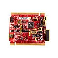
TOWER SYSTEM BOARD MCF51MM
Manufacturer
Freescale Semiconductor
Series
ColdFire®, Flexis™r
Type
MCUr
Specifications of TWR-MCF51MM
Contents
Board, 3 Modules, MED-EKG Kit, Cables, Documentation, DVD
Product
Microcontroller Modules
Data Bus Width
32 bit
Core Processor
MCF51MM
Clock Speed
32 KHz
Interface Type
RS232, RS485, CAN , USB
Flash
256 KB
Operating Supply Voltage
3.3 V
Silicon Manufacturer
Freescale
Core Architecture
Coldfire
Core Sub-architecture
Coldfire V1
Silicon Core Number
MCF51
Silicon Family Name
Flexis - MCF51MM
Rohs Compliant
Yes
For Use With/related Products
Freescale Tower System, MCF51MM
Lead Free Status / RoHS Status
Lead free / RoHS Compliant


3.4
An RS232 transceiver on the TWR-MCF51MM connects to a standard 2x5 pin header (refer to Figure 2).
Selection jumpers J15 and J16 allow MCF51MM256 SCI2 signals to be routed to either the RS232
transceiver or the OSBDM circuit. Refer to Figure 5 for more details.
Alternatively, when assembled as a Tower System, the MCF51MM256 SCI1 TX and RX are routed to the
SER-TWR. If the SER-TWR jumpers are configured to run in RS-232 mode, the SCI1 TX and the RX signal
can be communicated via the RS232 connector from the TWR-SER. Please refer to the TWE-SER user
manual (TWRSERUM) from
3.5
The TWR-MCF51MM implements an infrared transmit and receive port. The transmit circuit is
implemented with an infrared diode and the user can choose to drive the diode either with IRO or SCI
TX. The receiver is implemented by an infrared transistor and the user can choose to input this signal
to the SCI RX or the ACMP input. Jumpers J9, J25 and J26 are used for routing the connections, refer to
Section 4 to set the jumpers. Please refer to application note AN4116, searchable from
www.freescale.com
3.6
The TWR-MCF51MM features a 2x10 expansion connector J27 (refer to Figure 3) to MED-EKG for
routing the medical engine signals to external medical board so it can use the OPAMP, TRIAMP, ADC
and DAC on MCF51MM to implement the requirement signal conditioning for medical applications.
When the DSC MC56F8006 from the MED-EKG is enabled, MCF51MM256 can choose to read the
conditioned EKG results output from the DSC via I2C transmission (pin 3 and pin 4). To enable I2C
communication, you must assemble the MEG-EKG with the Tower System because the TWR-SER has
the pulled up resistors circuit required for I2C transmission.
In Figure 3, the bold text highlights the functions that are used to implement the MED-EKG
demonstration. For detail about the MED-EKG, please refer to the MED-EKG user manual, MED-EKG lab
and schematic included in the TWR-MCF51MM-KIT or TWR-S08MM128-KIT. All these are also available
on Freescale.com/tower
RS232 Interface
Infrared Port
Medical Connector
www.freescale.com/tower
Figure 2. RS232 2x5 Pin Header Connections
MCF51MM256
Not Connected
Not Connected
Signal
TWR-MCF51MM User Manual
GND
RX2
TX2
1
3
5
7
9
Pin
10
2
4
6
8
for more detail.
MCF51MM256
Not Connected
Not Connected
Not Connected
Not Connected
3.3V
Signal
Page 5 of 12
Related parts for TWR-MCF51MM
Image
Part Number
Description
Manufacturer
Datasheet
Request
R

Part Number:
Description:
Power Management IC Development Tools Low-volt 3-phase MC
Manufacturer:
Freescale Semiconductor
Datasheet:
Part Number:
Description:
K53N512CMD100 TWR Module
Manufacturer:
Freescale Semiconductor
Datasheet:
Part Number:
Description:
TWR-K53N512 Dev Kit
Manufacturer:
Freescale Semiconductor
Datasheet:

Part Number:
Description:
CONV DC/DC TRI OUT 5,15,-15V
Manufacturer:
Murata Power Solutions Inc
Datasheet:

Part Number:
Description:
CONV DC/DC TRI OUT 5,12,-12V
Manufacturer:
Murata Power Solutions Inc
Datasheet:

Part Number:
Description:
CONV DC/DC TRI OUT 5,15,-15V
Manufacturer:
Murata Power Solutions Inc
Datasheet:

Part Number:
Description:
LCD MODULE FOR TWR SYSTEM
Manufacturer:
Freescale Semiconductor
Datasheet:

Part Number:
Description:
DC/DC TH 11W 5-5/12V Triple A
Manufacturer:
Murata Power Solutions Inc
Datasheet:


Part Number:
Description:
TOWER SYSTEM PROTO
Manufacturer:
Freescale Semiconductor
Datasheet:

Part Number:
Description:
TOWER ELEVATOR BOARDS HARDWARE
Manufacturer:
Freescale Semiconductor
Datasheet:

Part Number:
Description:
TOWER SERIAL I/O HARDWARE
Manufacturer:
Freescale Semiconductor
Datasheet:

Part Number:
Description:
TOWER SYSTEM BOARD MPC5125
Manufacturer:
Freescale Semiconductor
Datasheet: