TWR-MPC5125 Freescale Semiconductor, TWR-MPC5125 Datasheet
TWR-MPC5125
Specifications of TWR-MPC5125


Related parts for TWR-MPC5125


TWR-MPC5125 Summary of contents
Page 1
... TWR-MPC5125 User Manual ...
Page 2
... TWR-MPC5125 User Manual semiconductor Table of Contents 1.0 General Description 1.1 Device Placement and Functions 2.0 Hardware Design & Architecture 2.1 General Description 2.2 Physical Specifications 2.3 Debugger Interface 2.4 Physical Specifications 3.0 Control & Configuration 3.1 Switch Settings 3.2 Sw7 – Power On Reset 3.3 Sw1 – ...
Page 3
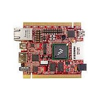
... TWR-MPC5125 User Manual semiconductor 1.0 General Description The MPC5125 Tower System is based on Freescale's MPC5125 microprocessor. The board provides on-board DDR2 SDRAM, NAND FLASH,CAN ports, USB 2.0, 10/100 Ethernet, HDMI,USB Debug Port.All powered from a 5 Volt wall mount power supply. Freescale's Tower System. For information of Tower System, please go to http://www ...
Page 4
... TWR-MPC5125 User Manual semiconductor U10 NAND Flash Memory 28 U4 Digital Accelerometer 29 Additional descriptions of the functionality of switches and jumpers along with their recommended settings can be found in Section 3 of this manual. J2- JTAG Connector 1 Connector 16-pin header used for the COP/JTAG input. This port is made available to aid of debugging code running on the MPC5125 ...
Page 5
... TWR-MPC5125 User Manual semiconductor Cn1 RJ45 Ethernet Connector 2 Cn1 is a standard Ethernet input jack J35 Serial Port Header 3 J35 is the serial port header with the following 2x2 header to MPC5125 pin assignments: PSC2_2 PSC2_3 SW1 System config switch 4 See switch settings. Section 3 ...
Page 6
... TWR-MPC5125 User Manual semiconductor J3 On-Board Microphone (MIC) 10 Audio input J1 Earphone Connector 11 Audio output U28 Audio CODEC 12 U28 is Audio CODEC Secondary Elevator Connctor 13 Secondary Elevator Edge Connector for the Freescale TOWER system Primary Elevator connector 14 Primary Elevator Edge Connector for the Freescale TOWER system ...
Page 7
... TWR-MPC5125 User Manual semiconductor SW8 Hibernate Switch 19 SW8 is hibernate switch Push it to wake up the system J33 Depopulated Battery Site 20 Location to add a battery or capacitor for the Real Time Clock VBAT_RTC power domain.Recommended capacitor is EECEN0F204RT from Panasonic . U1 MPC5125 Freescale's MPC5125 microprocessor SD Card Connector ...
Page 8
... TWR-MPC5125 User Manual semiconductor 2.0 Hardware Design & Architecture 2.1 Memory 4GB MLC NAND flash storage 256MB DDR2 memory 2.2 Connectving & Features Digital accelerometer - HDMI(video/audio) port with HDMI to DVI--D adaptor - RJ-45 10/100 Base T Ethernet port - Mini-AB USB2.0 OTG USB host to hub (keyboard, mouse, sound , card, WiFi,....) ...
Page 9
... TWR-MPC5125 User Manual semiconductor 2.4 Physical Specifications This section contains general information on the MPC5125's physical characteristics Board Size: Freescale Tower specification(59mm x 90mm) Power Requirement: 5VDC Operating Temperature: 0℃ to +70℃ Weight: 50g RoHS: Compliant FCC/CE: Compliant TWR-MPC 5125 LAN PHY Made by www ...
Page 10
... TWR-MPC5125 User Manual semiconductor 3.0 Control & Configuration This section contains general set-up information about the various jumpers, switches on the MPC5125 board. 3.1 Switch Settings This section provides a brief description of the functionality and recommended settings for the switches located on the MPC5125 Refer to Figure 1 for the locations of these switches. 3.2 Sw7 – ...
Page 11
... TWR-MPC5125 User Manual semiconductor 3.4 Configuration Header Settings 3.4.1 J4 USB Debug Port Mode This Jump is function select: 1-2 Short USB Debug Port 1-2 Open Serial to USB bridge 3.4.2 J4 Debug MCU mode 3-4 Short Bootloader mode 3-4 Open UART to USB bridge mode ...
Page 12
... TWR-MPC5125 User Manual semiconductor 4.0 Schematic The schematic and basic assembly information in a portable document format for the MPC5125 can be located on the CD with the board. The MPC5125 design can be customized for optional flexibility and custom interfaces so the embedded systems engineer can obtain a lower overall parts cost using a variety of fixed and user selectable options ...
Page 13
... TWR-MPC5125 User Manual semiconductor 5.0 Operation 5.1 Central Processing Unit The MCP5125 provides the interface to local on board resources including: NAND FLASH memory, DDR2-SDRAM memory, MII (10/100 Fast Ethernet Controller), RMII (10/100 Fast Ethernet Controller), I2C (EEPROM), PSC (programmable serial controller) for RS232 and AC97 (audio), Interrupt controller, USB 2 ...
Page 14
... TWR-MPC5125 User Manual semiconductor The RTC_CLK_32.768Khz is used by the CPU's internal XTAL_RTC drive circuitry. 5.4 Memory 5.4.1 DDR2 SDRAM The dedicated DDR2 memory bus is 32 bits wide, single bank, 200MHz clock frequency, no ECC. It uses the MPC5125 DDR2 SDRAM controller and is directly connection to the MPC5125. ...
Page 15
... TWR-MPC5125 User Manual semiconductor 6.0 U-boot, Linux setup 6.1 Host Computer Setup Host computer setup is critical for your BSP to function. The host must be running tftp and nfs servers in order for deployment to work. The following instructions are generic. Your system may be different and the commands should be adjusted accordingly ...
Page 16
... TWR-MPC5125 User Manual semiconductor protocol = udp wait = yes user = root server = /usr/sbin/in.tftpd server_args =/tftpboot } 9). Restart the nfs and tftp servers on your host computer $ sudo /etc/init.d/xinetd restart $ sudo /etc/init.d/nfsserver restart 6.2 Target Setup 1). Connect your board to the network via the Ethernet port. ...
Page 17
... TWR-MPC5125 User Manual semiconductor 6.3 Configuring U-Boot To boot the Linux kernel u-boot must have device tree support compiled in. To verify this support is enabled, type help bootm at the u-boot prompt. => help bootm bootm [addr [arg ...]] - boot application image stored in memory passing arguments 'arg ...'; when booting a Linux kernel, 'arg' can be the ...
Page 18
... TWR-MPC5125 User Manual semiconductor fdt_addr=FC2C0000 ramdisk_addr=FC300000 u-boot=ads5125/u-boot.bin netdev=eth0 nfsargs=setenv bootargs root=/dev/nfs rw nfsroot=${serverip}:${rootpath} ramargs=setenv bootargs root=/dev/ram rw addip=setenv bootargs ${bootargs}ip=${ipaddr}:${serverip}:${gatewayip}:${netmask}:${hostname}:$ {netdev}:off panic=1 addtty=setenv bootargs ${bootargs}console=${consdev},${baudrate} flash_nfs=run nfsargs addip addtty;bootm ${kernel_addr}- ${fdt_addr} flash_self=run ramargs addip addtty ...
Page 19
... TWR-MPC5125 User Manual semiconductor ipaddr=192.168.10.205 serverip=192.168.10.227 kernel_addr_r=3000000 fdt_addr_r=4000000 ramdisk_addr_r=5000000 rootpath=/home/tony/nfs consdev=ttyPSC1 fdtfile=mpc5125-twr.dtb bootfile=vmlinux-5125-twr.bin stdin=serial stdout=serial stderr=serial Environment size: 1947/131067 bytes If your u-boot environment does not match then use the u-boot setenv command to add or modify it to match what is printed here. 2). Tell the linux kernel which serial port to use for a console from the kernel command line ...
Page 20
... TWR-MPC5125 User Manual semiconductor 5). Save the configuration to flash => saveenv 6.4 NFS Root Development Deployment During developement one typically downloads the kernel via tftp and uses nfs for the root filesystem. 1). On the host, copy the kernel and device tree file to the tftpboot directory 2). Set nfsboot parameter => ...
Page 21
... TWR-MPC5125 User Manual semiconductor 2). Set net_ramboot parameter => set net_ramboot 'setenv bootargs root=/dev/ram rw console=$consdev,$baudrate;tftp $kernel_ld_addr $kernel_name;tftp $fdt_ld_addr $fdt_name;tftp $ramdisk_ld_addr $ramdisk_name;bootm $kernel_ld_addr $ramdisk_ld_addr $fdt_ld_addr' => setenv kernel_ld_addr 0x2000000 => setenv fdt_ld_addr 0x2800000 => setenv ramdisk_ld_addr 0x3000000 => setenv kernel_name vmlinux-5125-twr.bin => setenv fdt_name mpc5125-twr.dtb => setenv ramdisk_name rootfs.ext2.gz.uboot-common => ...
Page 22
... TWR-MPC5125 User Manual semiconductor 7.0 How to build U-Boot, Kernel and device-tree 7.1 Cross-compilation settings 1). Install cross compiler tool chains Tools install from the LTIB package, you can refer to the LTIB help documentation for detailed installation instructions 2). Before cross compiling anything, you must set the environment variable: ARCH, CROSS_COMPILE and PATH. Set environment variables script file " ...
Page 23
... TWR-MPC5125 User Manual semiconductor Compressed kernel ulmage in the path: arch/powerpc/boot/uImage Uncompress the kerenl uImage script file "mkvm": #!/bin/bash cat vmlinux.bin.gz | gunzip > vmlinux.bin mkimage -A ppc -O Linux -T kernel -C none -a 0x0 -e 0x0 -n Linux-2.6 -d vmlinux.bin $1 $ mkvm vmlinux-5125-twr.bin 3). Build Device-tree Compile the DTS script file "mkdts": ...
Page 24
... TWR-MPC5125 User Manual semiconductor 8.0 How to program NAND 8.1 Program Loader and U-boot There are two ways, using CodeWarrior JTAG port program NAND, from CodeWarrior for MobileGT IDE or from CodeWarrior Connection Server command line script. 8.1.1 IDE method What tools are needed: · ...
Page 25
... TWR-MPC5125 User Manual semiconductor If prompt “can't find the file libgcc2.c”, select “Continue with next file”, this tip does not affect the previous work. 2). Settings: Edit->Default Project Settings Target Settings Panels->Debugger->EPPC Debugger Settings: Processor: 52xx Use Target Initialization File: 5125-twr-init.cfg, this is important initialization DDR parameters ...
Page 26
... TWR-MPC5125 User Manual semiconductor 3). Press F5, start to run u-boot, serial port will see the u-boot bootup message, entery command line. 4). Copy nand_spl/u-boot-spl-2k.bin and u-boot-second.bin to /tftpboot. 5). Program loader: => tftp 0x4000000 u-boot-spl-2k.bin => nand_e 0x00 0x01 => nand_loader 0x4000000 0x00 0x800 (file size) => nand_r 0x2000000 0x00 0x800 => ...
Page 27
... TWR-MPC5125 User Manual semiconductor 8.2 Program Device-tree and Kernel 1). Device-tree => setenv fdt_name mpc5125-twr.dtb => setenv flash_dtb 0xb00 => tftp 0x3000000 $fdt_name => nand_e $flash_dtb 0xb01 => nand_w 0x3000000 $flash_dtb 0x3000 2). Kernel => setenv kernel_name vmlinux-5125-twr.bin => setenv flash_kernel 0x300 => tftp 0x3000000 $kernel_name => nand_e $flash_kernel 0xaff => nand_w 0x3000000 $flash_kernel 0x400000 (file size) 8 ...
Page 28
... TWR-MPC5125 User Manual semiconductor $ sudo flash_eraseall /dev/mtd6 $ sudo mkdir -p /tmp/udisk /tmp/mtd $ sudo mount -t vfat /dev/sda1 /tmp/udisk $ sudo mount -t yaffs2 /dev/mtdblock6 /tmp/mtd $ sudo tar xpf /tmp/udisk/<ROOTFS_PACKAGE>.tar -C /tmp/mtd $ sudo umount /tmp/mtd $ sudo umount /tmp/udisk TWR-MPC 5125 Made by www. .com 27 ...
Page 29
... TWR-MPC5125 User Manual semiconductor Appendix A J2 – MPC5125 JTAG (16 pin Header) Pin No Description MPC JTAG COP TDO MPC JTAG COP TDI 3 MPC JTAG TRST 3. MPC JTAG TCK MPC JTAG TMS MPC SRESET 12 GND 13 HRESET NC 14 MPC CKSTP OUT 15 16 GND TWR-MPC 5125 – ...
Page 30
... TWR-MPC5125 User Manual semiconductor Appendix B The following memory map is only an example, refer to the MPC5125 Quick Guide for specific memory map configurations, many of these memory map settings are user defined. Bytes Function Reserved IMMRBAR Default setting at reset FF40 0000 DDR SDRAM 256MB ...
Page 31
Made by www. .com ...