TWR-MPC5125 Freescale Semiconductor, TWR-MPC5125 Datasheet - Page 10
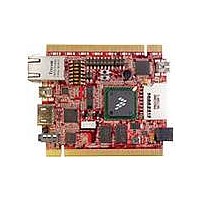
TWR-MPC5125
Manufacturer Part Number
TWR-MPC5125
Description
TOWER SYSTEM BOARD MPC5125
Manufacturer
Freescale Semiconductor
Type
MCUr
Specifications of TWR-MPC5125
Contents
Board
Processor To Be Evaluated
MPC5125
Data Bus Width
32 bit
Interface Type
Ethernet, USB, HDMI
Maximum Operating Temperature
+ 125 C
Minimum Operating Temperature
- 40 C
Silicon Manufacturer
Freescale
Core Architecture
Power Architecture
Core Sub-architecture
Power Architecture
Silicon Core Number
MPC5xxx
Silicon Family Name
MobileGT
Rohs Compliant
Yes
For Use With/related Products
Freescale Tower System
Lead Free Status / RoHS Status
Lead free / RoHS Compliant


3.0 Control & Configuration
This section contains general set-up information about the various jumpers,
switches on the MPC5125 board.
3.1 Switch Settings
This section provides a brief description of the functionality and recommended
settings for the switches located on the MPC5125
Refer to Figure 1 for the locations of these switches.
3.2 Sw7 – Power On Reset
Sw7 is a push button that provides a power on reset signal for the hardware
on the MPC5125.
3.3 Sw1 – Boot Mode
The mode switch provides configure the different operation of the MPC5125.
SW1 Position Reset Configuration
6
5
4
3
2
TWR-MPC 5125
1
semiconductor
RST_CONF_ROMLOC0
RST_CONF_BMS
RST_CONF_LPC_DBW0
RST_CONF_LPC_DBW1
RST_CONF_LPCWA
RST_CONF_LPCMX LPC
TWR-MPC5125 User Manual
Signal Description
Boot Device Select
0 = LPC Boot, 1 = NAND (NFC) boot
Boot Mode Select
0 = boot low, 1 = boot high
LPC Data Port Size
00 = 8-bit, 01 = 16-bit, 10 = reserved, 11 = 32-bit
LPC Word/Byte Address Mode
0 = word address mode, 1 = byte address mode
Multiplex Mode
0 = non-multiplexed mode, 1 = multiplexed mode
Made by
www.
1
Default
1
1
0
00
.com
0 9
Related parts for TWR-MPC5125
Image
Part Number
Description
Manufacturer
Datasheet
Request
R

Part Number:
Description:
K53N512CMD100 TWR Module
Manufacturer:
Freescale Semiconductor
Datasheet:
Part Number:
Description:
TWR-K53N512 Dev Kit
Manufacturer:
Freescale Semiconductor
Datasheet:

Part Number:
Description:
CONV DC/DC TRI OUT 5,15,-15V
Manufacturer:
Murata Power Solutions Inc
Datasheet:

Part Number:
Description:
CONV DC/DC TRI OUT 5,12,-12V
Manufacturer:
Murata Power Solutions Inc
Datasheet:

Part Number:
Description:
CONV DC/DC TRI OUT 5,15,-15V
Manufacturer:
Murata Power Solutions Inc
Datasheet:

Part Number:
Description:
LCD MODULE FOR TWR SYSTEM
Manufacturer:
Freescale Semiconductor
Datasheet:

Part Number:
Description:
DC/DC TH 11W 5-5/12V Triple A
Manufacturer:
Murata Power Solutions Inc
Datasheet:


Part Number:
Description:
TOWER SYSTEM PROTO
Manufacturer:
Freescale Semiconductor
Datasheet:

Part Number:
Description:
TOWER ELEVATOR BOARDS HARDWARE
Manufacturer:
Freescale Semiconductor
Datasheet:

Part Number:
Description:
TOWER SERIAL I/O HARDWARE
Manufacturer:
Freescale Semiconductor
Datasheet:

Part Number:
Description:
TOWER SYSTEM KIT MPC5125
Manufacturer:
Freescale Semiconductor
Datasheet:

Part Number:
Description:
TOWER SYSTEM BOARD K40X256
Manufacturer:
Freescale Semiconductor
Datasheet: