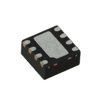
SKY65084-360LF Skyworks Solutions Inc, SKY65084-360LF Datasheet - Page 3

SKY65084-360LF
Manufacturer Part Number
SKY65084-360LF
Description
IC AMP 1.5-2.4GHZ LN 8QFN
Manufacturer
Skyworks Solutions Inc
Datasheet
1.SKY65084-360LF.pdf
(11 pages)
Specifications of SKY65084-360LF
Current - Supply
65mA
Frequency
1.5GHz ~ 2.4GHz
Gain
25dB
Noise Figure
0.7dB
P1db
16dBm
Package / Case
8-VQFN Exposed Pad
Rf Type
CDMA, GSM, WCDMA
Test Frequency
1.95GHz
Voltage - Supply
4.75 V ~ 5.25 V
Lead Free Status / RoHS Status
Lead free / RoHS Compliant
Other names
863-1269-2
Available stocks
Company
Part Number
Manufacturer
Quantity
Price
Part Number:
SKY65084-360LF
Manufacturer:
SKYWORKS/思佳讯
Quantity:
20 000
Source Inductance
The effect of source inductance varies with frequency. Too little
source inductance increases gain and high frequency stability, but
at the cost of more in-band instability. Too much source
inductance decreases high frequency stability and gain, but
improves in-band instability. It is very important to find the
optimum tuning of source inductance that balances all variables.
The board trace present on the first stage transistor (pin 3) is
about 60 mils long and 6 mils wide. The electrical length of the
line is 9.8 degrees at 1950 MHz. When designing a board for the
SKY65084-360LF, these exact dimensions should be used. The
board trace length at pin 4 should be minimized.
Input and Output RF Matching Network
The input band-pass matching network consists of four
components. Component C1 serves as the input DC blocking
capacitor, C2 provides high frequency stability and improved input
return loss, and L1 and L2 are responsible for the best noise
match looking into the gate of the first stage amplifier.
Excess board trace should be eliminated at the input of the device
to minimize board losses. High-Q components should be used to
achieve the best NF of the amplifier. Murata GJM series
capacitors and Coilcraft HP series inductors are recommended.
Any excess board or component loss on the input of the device
directly adds to the total measured NF.
The output matching network is band-pass network optimized for
output return loss and OIP3 performance. No High-Q components
are required for output matching or DC bias.
Table 2. SKY65084-360LF Absolute Maximum Ratings
CAUTION: Although this device is designed to be as robust as possible, Electrostatic Discharge (ESD) can damage this device. This device
Note: Exposure to maximum rating conditions for extended periods may reduce device reliability. There is no damage to device with only one parameter set at the limit and all other
Supply voltage
Input power
Supply current stage one
Supply current stage two
Power dissipation
Junction temperature
Storage temperature
Operating temperature
Thermal resistance
parameters set at or below their nominal value. Exceeding any of the limits listed here may result in permanent damage to the device.
must be protected at all times from ESD. Static charges may easily produce potentials of several kilovolts on the human body
or equipment, which can discharge without detection. Industry-standard ESD precautions should be used at all times.
Parameter
Skyworks Solutions, Inc. • Phone [781] 376-3000 • Fax [781] 376-3100 • sales@skyworksinc.com • www.skyworksinc.com
201107E • Skyworks Proprietary Information • Products and Product Information are Subject to Change Without Notice • March 31, 2010
V
P
I
I
P
T
T
T
Θ
DS
DS
DD
J
STG
OP
IN
DIS
JC
1
2
1
, V
Symbol
DD
2
Minimum
–65
–40
Feedback
Using feedback on the SKY65084-360LF is not necessary, but
can be used to reduce gain without affecting other parameters.
The default circuit configuration has 25 dB of gain, but can be
decreased to about 18 dB by adding feedback components.
Measuring NF
Special care should be taken when making < 1 dB NF
measurements. Ideally, measurements should be made in an RF
shield room. An Agilent MXA N9020A spectrum analyzer with an
internal pre-amp paired with an N4001A smart noise source was
used for all noise measurements. The smart noise source has an
internal thermocouple that automatically sets the T
the analyzer. If a smart noise source is unavailable, a standard
noise source should be used. Use an external thermocouple to
manually adjust the T
Electrical and Mechanical Specifications
The absolute maximum ratings of the SKY65084-360LF are
provided in Table 2. The recommended operating conditions are
specified in Table 3 and electrical specifications are provided in
Table 4.
Performance characteristics for the SKY65084-360LF are
illustrated in Figures 4 through 10.
DATA SHEET • SKY65084-360LF LOW NOISE AMPLIFIER
Typical
+13
100
530
150
5.5
50
47
COLD
setting to ensure accurate results.
Maximum
+125
+85
COLD
Units
C/W
dBm
mW
mA
mA
C
C
C
setting on
V
3


