AD8302ARU-REEL Analog Devices Inc, AD8302ARU-REEL Datasheet - Page 20
AD8302ARU-REEL
Manufacturer Part Number
AD8302ARU-REEL
Description
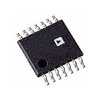
IC DETECTOR RF/IF 14-TSSOP T/R
Manufacturer
Analog Devices Inc
Datasheet
1.AD8302ARUZ.pdf
(24 pages)
Specifications of AD8302ARU-REEL
Rohs Status
RoHS non-compliant
Frequency
2.7GHz
Rf Type
General Purpose
Input Range
-60dBm ~ 0dBm
Accuracy
0.5dB
Voltage - Supply
2.7 V ~ 5.5 V
Current - Supply
23mA
Package / Case
14-TSSOP (0.173", 4.40mm Width)
Pin Count
14
Screening Level
Industrial
Package Type
TSSOP
Lead Free Status / Rohs Status
Not Compliant
Available stocks
Company
Part Number
Manufacturer
Quantity
Price

Part Number:
AD8302ARU-REEL7
Manufacturer:
ADI/亚德诺
Quantity:
20 000


AD8302
Reflectometer
The AD8302 can be configured to measure the magnitude ratio
and phase difference of signals that are incident on and reflected
from a load. The vector reflection coefficient, , is defined as,
where Z
teristic system impedance.
The measured reflection coefficient can be used to calculate the
level of impedance mismatch or standing wave ratio (SWR) of a
particular load condition. This proves particularly useful in diag-
nosing varying load impedances such as antennas that can degrade
performance and even cause physical damage. The vector
reflectometer arrangement given in Figure 13 consists of a pair
of directional couplers that sample the incident and reflected sig-
nals. The attenuators reposition the two signal levels within the
dynamic range of the AD8302. In analogy to Equations 15 and
16, the attenuation factors and coupling coefficients are given by:
where
negative for passive loads. Consider the case where the incident
signal is 10 dBm and the nominal reflection coefficient is –19 dB.
As shown in Figure 13, using 20 dB couplers on both sides and
–30 dBm for P
are 1 dB and 20 dB, respectively. The magnitude and phase of
the reflection coefficient are available at the VMAG and VPHS
pins scaled to 30 mV/dB and 10 mV/degree. When
the VMAG output is 900 mV.
Γ =
C
C
B
Re
A
+
+
flected Voltage / Incident Voltage
L
NOM
L
L
is the complex load impedance and Z
B
A
=
=
is the nominal reflection coefficient in dB and is
P
P
OPT
IN
IN
, the attenuators for Channel A and B paths
−
+
P
Γ
OPT
NOM
−
P
OPT
=
(
Z
L
−
Z
O
O
)
/ Z
is the charac-
(
L
is –19 dB,
+
Z
O
)
(18)
(19)
(17)
–20–
The measurement accuracy can be compromised if board
level details are not addressed. Minimize the physical distance
between the series connected couplers since the extra path
length adds phase error to . Keep the paths from the couplers
to the AD8302 as well matched as possible since any differences
introduce measurement errors. The finite directivity, D, of the
couplers sets the minimum detectable reflection coefficient, i.e.,
|
Γ
MIN
Figure 13. Using the AD8302 to Measure the Vector
Reflection Coefficient Off an Arbitrary Load
SOURCE
(dB)|<|D(dB)|.
INCIDENT
WAVE
C3
C5
R2
C6
20dB
1
2
3
4
5
6
7
COMM
INPA
OFSA
VPOS
OFSB
INPB
COMM
AD8302
C4
1dB
R1
C1
VMAG
MSET
MFLT
VREF
VPHS
PSET
PFLT
REFLECTED
14
13
12
11
10
R4
9
8
C2
WAVE
C8
C7
R5
R6
VP
Z
REV. A
LOAD
Related parts for AD8302ARU-REEL
Image
Part Number
Description
Manufacturer
Datasheet
Request
R

Part Number:
Description:
IC DETECTOR RF/IF 14-TSSOP
Manufacturer:
Analog Devices Inc
Datasheet:
Part Number:
Description:
IC,Phase/Frequency Detector,BIPOLAR,TSSOP,14PIN,PLASTIC
Manufacturer:
Analog Devices Inc
Datasheet:

Part Number:
Description:
LF.2.7 GHz RF/IF Gain and Phase Detector
Manufacturer:
Analog Devices
Datasheet:

Part Number:
Description:
±1.7g Dual-Axis IMEMS Accelerometer Evaluation Board
Manufacturer:
Analog Devices Inc
Datasheet:

Part Number:
Description:
Inertial Sensor Evaluation System
Manufacturer:
Analog Devices Inc
Datasheet:
Part Number:
Description:
Manufacturer:
Analog Devices Inc
Datasheet:
Part Number:
Description:
Manufacturer:
Analog Devices Inc
Datasheet:
Part Number:
Description:
Manufacturer:
Analog Devices Inc
Datasheet:
Part Number:
Description:
Manufacturer:
Analog Devices Inc
Datasheet:
Part Number:
Description:
Manufacturer:
Analog Devices Inc
Datasheet:
Part Number:
Description:
Manufacturer:
Analog Devices Inc
Datasheet:
Part Number:
Description:
Manufacturer:
Analog Devices Inc
Datasheet: